The VCK190 evaluaon board uses power management ICs (PMIC) and power regulators from
Inneon Integrated Circuits to supply the core and auxiliary voltages listed in the following tables.
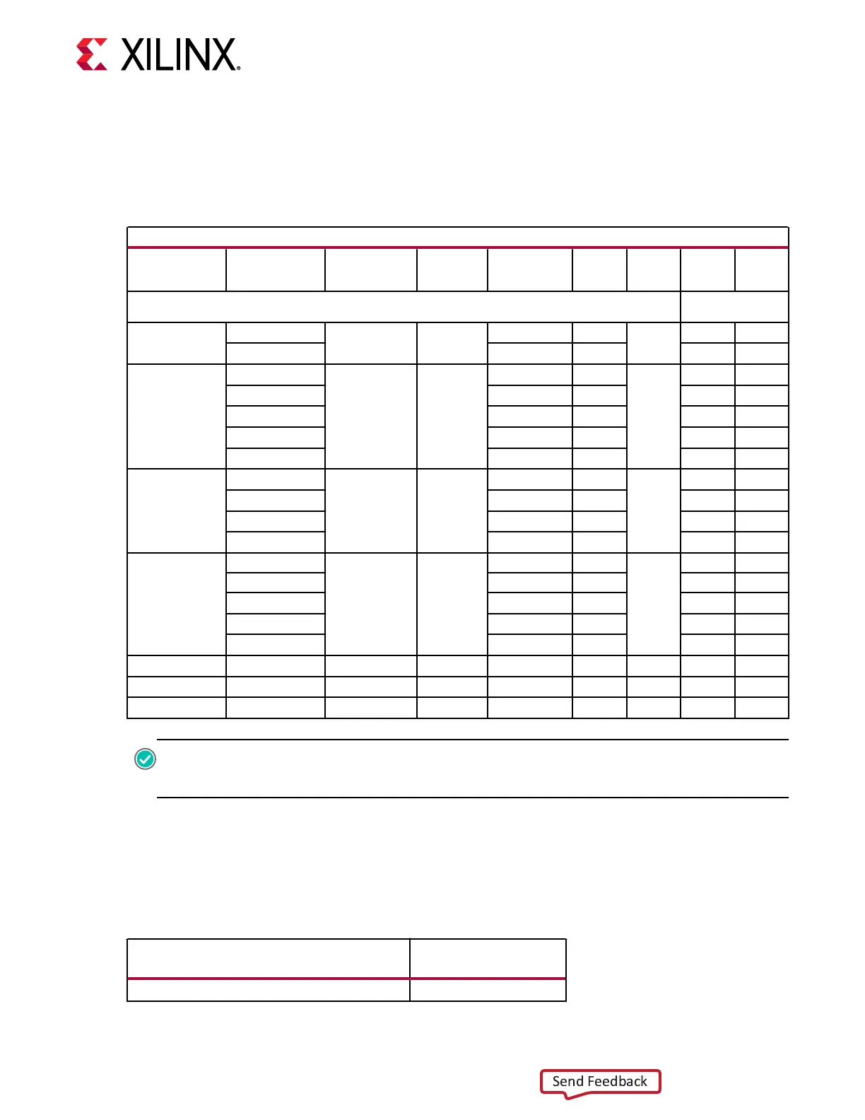
See schemac 038-05005-01.
Table 21: Power System - PMBus Regulators and INA226 Map
PMBus Regulators and INA226 Map
Schematic Page Rail Name Regulator Type U# Vout (V) Iout (A)
I2C
Address
INA226
U#
INA226
I2C
Address
PMBUS1(1),
PMBUS2(2)
57
VCCINT
IR35215 PMIC (6
Phase)
U152
0.80 190
0x16
U65
0x40(1)
VCC_SOC 0.80 18 U161
0x41(1)
61
VCC_PSLP
IRPS5401 (4
Phase + LDO)
U160
0.80 1
0x17
U165
0x44(1)
VCC_PSFP 0.80 2 U164
0x45(1)
VCCAUX 1.5 3 U166
0x40(2)
VCC_RAM_IO 0.80 4 U162
0x43(1)
VCCINT_PMC 0.80 0.5 U163
0x42(1)
63
VCCO_MIO
IRPS5401 (4
Phase + LDO)
U167
1.8 2
0x1C
U172
0x45(2)
VCC3V3 3.3 0.5 U174
0x47(2)
VCC1V8 1.8 6 U173
0x46(2)
VCCAUX_PMC 1.5 0.5 U168
0x41(2)
65
UTIL_1V13
IRPS5401 (4
Phase + LDO)
U175
1.13 1
0x1D
NA NA
UTIL_2V5 2.5 1 NA NA
VCC1V2_DDR4 1.2 4 U176
0x48(2)
VCC1V1_LP4 1.1 4 U177
0x49(2)
MGTYVCCAUX 1.5 0.5 U234
0x4D(2)
69 VADJ_FMC IR38164 U185 1.5 10
0x1E
U184
0x4A(2)
70 MGTYAVCC IR38164 U187 0.88 6
0x1F
U186
0x4B(2)
71 MGTYAVTT IR38164 U189 1.2 10
0x20
U188
0x4C(2)
RECOMMENDED: To ensure reliable operaon, Xilinx recommends running the report_power command
in the Vivado tools for designs targeng this board. The reported rail current requirements should do not
exceed the values listed in the following table.
The total device power should remain under 125W. To assist the Vivado tools in reporng when
power exceeds this amount, add this XDC constraint:
set_operating_conditions-design_power_budget 125 ;# (125W max power)
Table 22:
Device Rail Maximum Current
Device Rail
Maximum Current
(Amps)
VCCINT 190
Chapter 3: Board Component Descriptions
UG1366 (v1.0) January 7, 2021 www.xilinx.com
VCK190 Board User Guide 66

 Loading...


