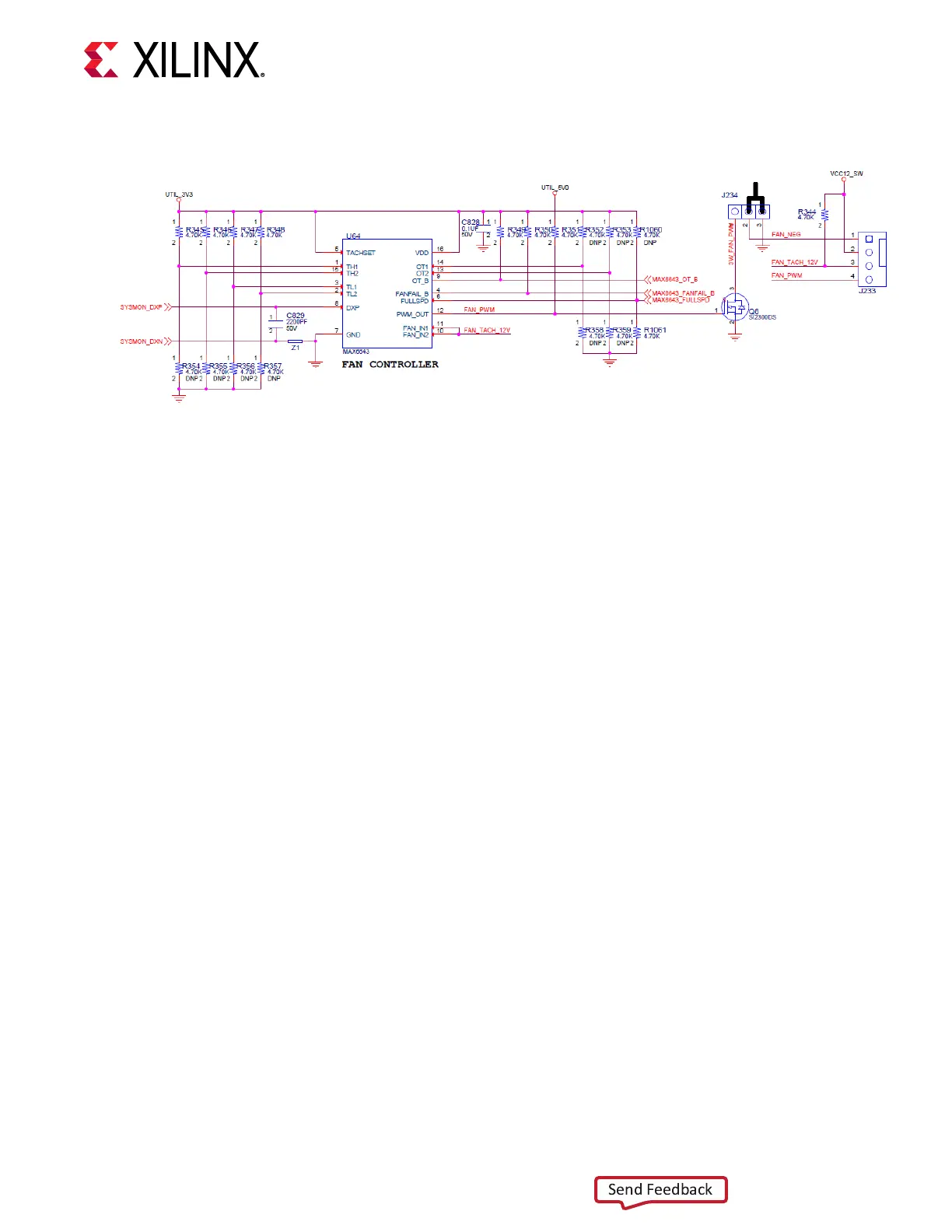
Figure 24: 12V Fan Header
X24956-121420
System Controller
[Figure 3, callout 48]
The VCK190 board includes an onboard System Controller. A host PC resident system controller
board user interface applicaon is provided on the VCK190 evaluaon board website. This board
user interface applicaon enables the query and control of select programmable features such as
clocks, FMC funconality, and power system parameters. The VCK190 website also includes a
tutorial on the board user interface applicaon and board setup instrucons.
A brief summary of these instrucons is provided here.
1. Ensure the Silicon Labs VCP USB-UART drivers are installed. See the Silicon Labs CP210x
USB-to-UART Installaon Guide (UG1033).
2. Download the board user interface host PC applicaon from the VCK190 evaluaon board
website.
3. Connect a USB cable to VCK190 USB-UART USB-C connector (J207).
4. Power-cycle the VCK190.
5. Launch the board user interface applicaon.
The board user interface applicaon UI is shown in the following gure.
Chapter 3: Board Component Descriptions
UG1366 (v1.0) January 7, 2021 www.xilinx.com
VCK190 Board User Guide 63

 Loading...


