Power On/Off Slide Switch
[Figure 3, callout 30]
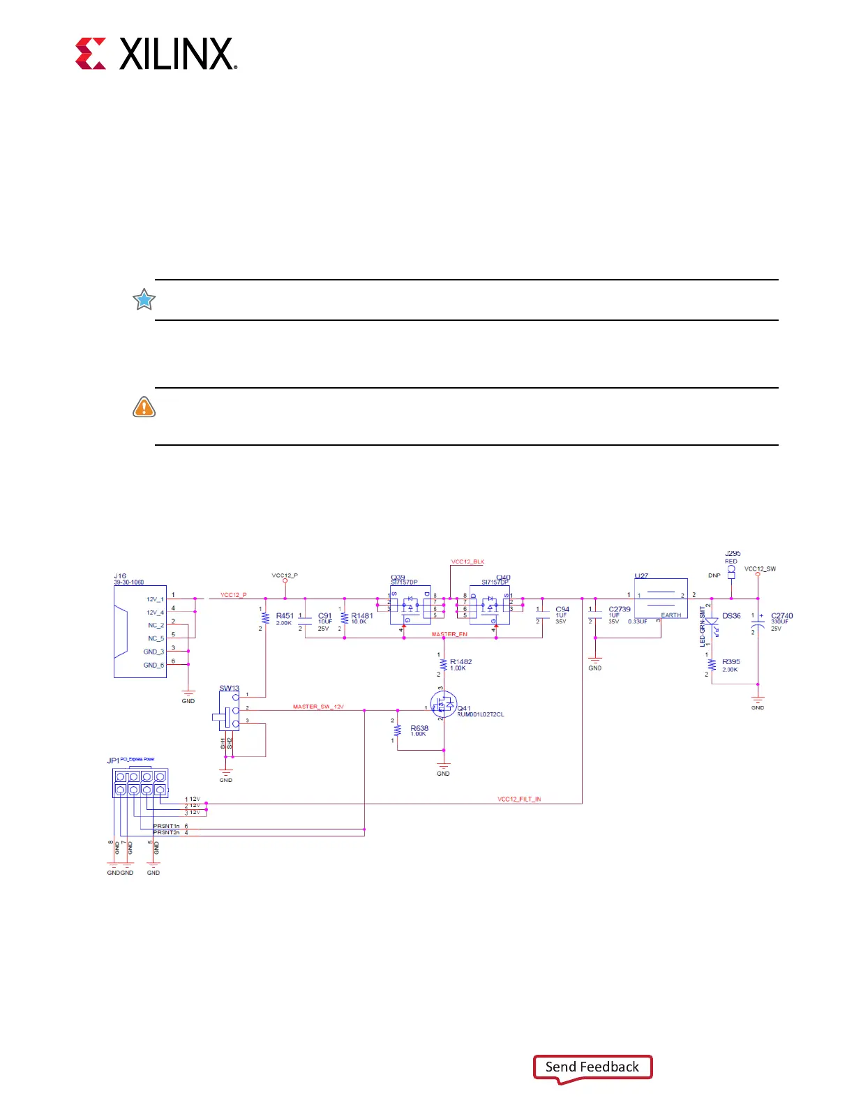
The VCK190 board power switch is SW13. Sliding the switch actuator from the o to the on
posion applies 12VDC power from either the 2x3 6-pin Mini-Fit power input connector J16
(power from an external 120VAC-to-12VDC power adapter) or the 2x4 8-pin ATX power supply
PCIe-type connector JP1.
IMPORTANT! Power to the VCK190 is mutually exclusive and only one of the two power connectors J16
or JP1 should be used to provide board power.
The green LED DS36 illuminates when the VCK190 board power switch is on. See Board Power
System for details on the onboard power system.
CAUTION! Do NOT plug a PC ATX power supply 6-pin connector into the VCK190 board power
connector J16. The ATX 6-pin connector has a dierent pinout than J16. Connecng an ATX 6-pin
connector into J16 damages the VCK190 board and voids the board warranty.
The following gure shows the power connector J16, power switch SW13, and LED indicator
DS36.
Figure 26: Power Input
X23276-100119
Board Power System
[Figure 3, callout 27]
Chapter 3: Board Component Descriptions
UG1366 (v1.0) January 7, 2021 www.xilinx.com
VCK190 Board User Guide 65

 Loading...


