APPLICATIONS OF Σ-SERIES PRODUCTS
3.6.7 Using Speed Loop Compensation Function
124
3.6.7 Using Speed Loop Compensation Function
1) This function compensates for the phase−delay generated by the digital control speed
detection. For this function, use the following constant.
Cn-28
NDBCC
Speed Loop
Compensation Constant
Unit:
Setting
Range: 0
to 100
Factory
Setting: 0
For Speed/Torque
Control Only
First, adjust the servo (position/speed loop gain, speed loop, integration time constant,
torque reference filter) appropriately in the “Cn−28 = 0” status.
Then, gradually increase the set value of Cn−28 from 0, find the proper value at which
noise and oscillation are minimal.
Note Use the speed loop compensation function (set value of Cn−28 is other than 0)
under the following status:
⋅ No servo system oscillation
⋅ No abnormal noise from the machine
Even if the speed loop compensation function is used, it may bring little effect or
even increase the oscillation. In these cases, stop using the speed loop com-
pensation function. (Set the value of Cn−28 to 0, again.)
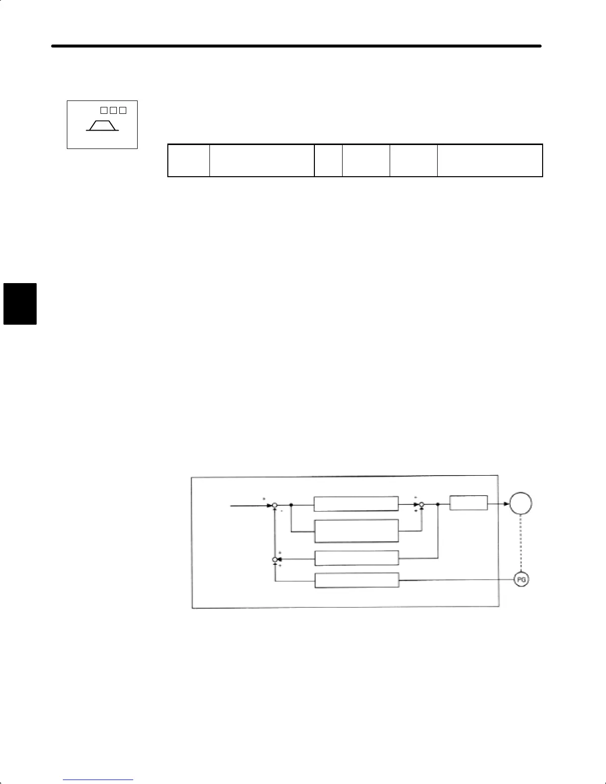
2) Speed loop compensation function can be illustrated by the following block diagram:
Speed
reference
Current loop gain (Cn−04)
Speed loop integration time
constant (Cn−05)
Current
loop
Speed calculation
* Compensation gain (K) is in proportion to the compensation constant (user
constant Cn−28). Cn−28 = 0 shows no compensation status.
Motor
Compensation gain K*
3
SGDA- S
Speed/Torque
 Loading...


