3.2Setting User Constants According to Host Controller
65
3.2 Setting User Constants According to Host Controller
This section describes how to connect a Σ-series Servo to a host controller and how to
set user constants.
3.2.1 Inputting Speed Reference 65........................................
3.2.2 Inputting Position Reference 69......................................
3.2.3 Using Encoder Output 73............................................
3.2.4 Using Contact I/O Signals 77........................................
3.2.5 Using Electronic Gear 79............................................
3.2.6 Using Contact Input Speed Control 83................................
3.2.7 Using Torque Control 88............................................
3.2.8 Using Torque Feed-forward Function 94...............................
3.2.9 Using Torque Restriction by Analog Voltage Reference 95...............
3.2.10 Using the Reference Pulse Inhibit Function (INHIBIT) 97.................
3.2.11 Using the Reference Pulse Input Filter Selection Function 99.............
3.2.1 Inputting Speed Reference
1) Input a speed reference by using the following input signal “speed reference input.” Since
this signal can be used in different ways, set the optimum reference input for the system
to be created.
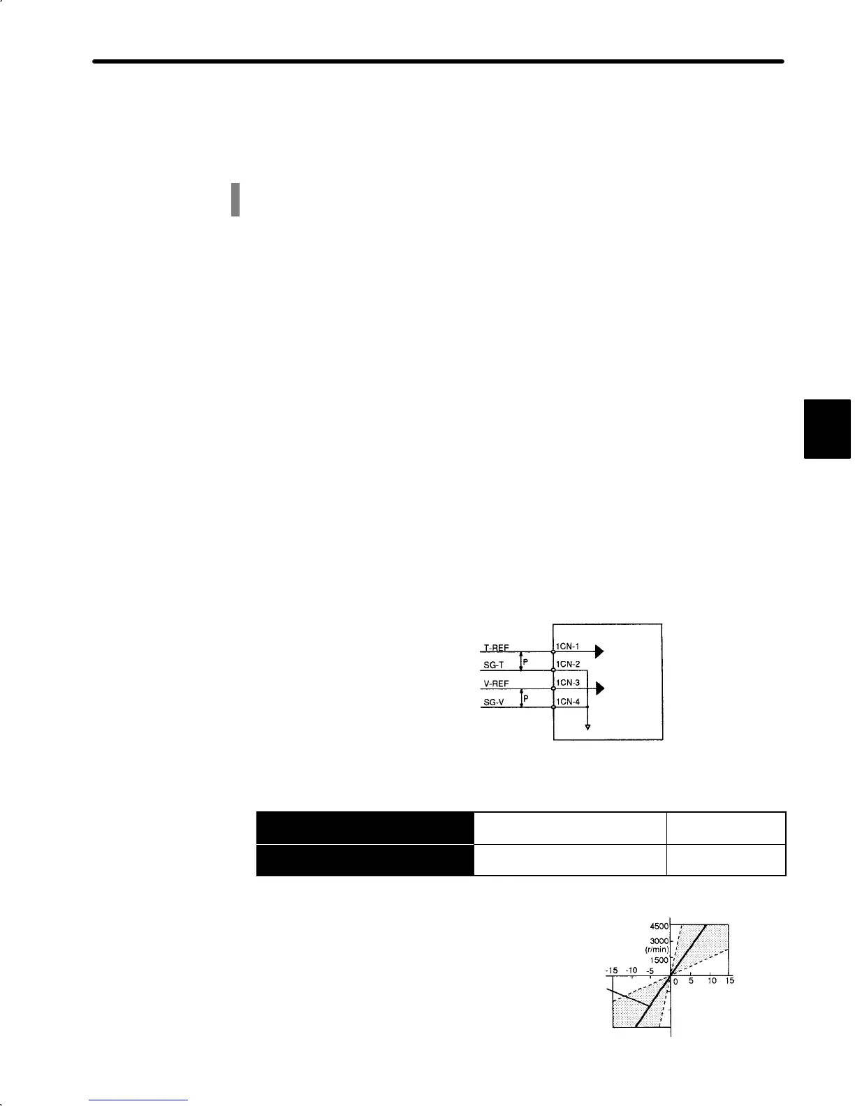
Torque reference input
(analog voltage input)
Speed reference input
(analog voltage input)
Servopack
Torque
reference
Speed
reference
↕P: Represents twisted-pair cables
→ Input V-REF 1CN-3
Speed Reference Input For Speed/Torque
Control Only
→ Input SG-V 1CN-4
Signal Ground for Speed
Reference Input
For Speed/Torque
Control Only
Use these signals when speed control is selected
(bits A and B of memory switch Cn-01).
For ordinary speed control, always wire the V-
REF and SG-V terminals.
Motor speed is controlled in proportion to the input
voltage between V-REF and SG-V.
3
Reference
speed
Standard
setting
Input voltage (V)
Set the slope in
Cn-03 (VREFGN).
−1500
−3000
−4500
 Loading...


