BASIC USES OF Σ-SERIES PRODUCTS
2.4.5 Minimum User Constants Required and Input Signals
48
2.4.5 Minimum User Constants Required and Input Signals
1) This section describes the minimum user constants that must be set to conduct a test run.
For details on how to set each user constant, refer to 4.1.5 Operation in User Constant
Setting Mode.
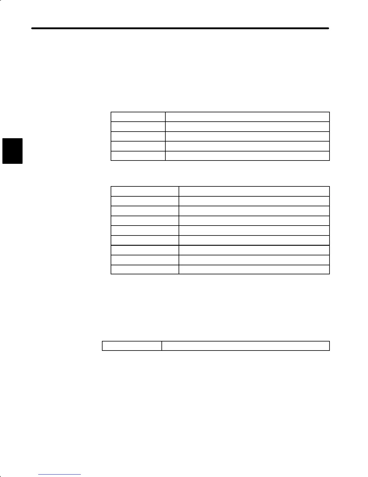
a) Servopack for speed/torque control
Cn-01 bit E
Encoder selection
Cn-02 bit 8 Motor selection
Cn-03 Speed reference adjustment gain
Cn-0A Encoder pulse dividing ratio
Cn-11 Number of encoder pulse
b) Servopack for position control
Cn-01 bit E
Encoder selection
Cn-02 bit 8 Motor selection
Cn-02 bits 3,4,5 Reference pulse form selection
Cn-02 bit D Logic of reference pulse
Cn-02 bit F Reference pulse output form
Cn-0A Encoder pulse dividing ratio
Cn-11 Number of encoder pulses
Cn-24 Electronic gear ratio (numerator)
Cn-25 Electronic gear ratio (denominator)
After changing the Cn-02 setting, always turn the power OFF, then ON. This makes
the new setting valid.
alone
2) If the specified direction of rotation differs from the actual direction of rotation, the wiring
may be incorrect. In this case, recheck the wiring and correct it accordingly. Then, if the
direction of rotation is to be reversed, set the following user constant:
Cn-02 (bit 0)
Reverse rotation mode (see page 54)
After changing the Cn-02 setting, always turn the power OFF, then ON. This makes the
new setting valid.
3) The following table lists the minimum input signals required to conduct a test run. For de-
tails of each input signal, refer to the relevant page.
2
 Loading...


