APPLICATIONS OF Σ-SERIES PRODUCTS
3.7.6 Handling of Power Loss
134
D TGON
(1CN-9)
D Status indication mode bit data
D Monitor mode Un-05 bit 4
User Constant Setting:
Memory switch Cn-01 bit 4 = 0
3.7.6 Handling of Power Loss
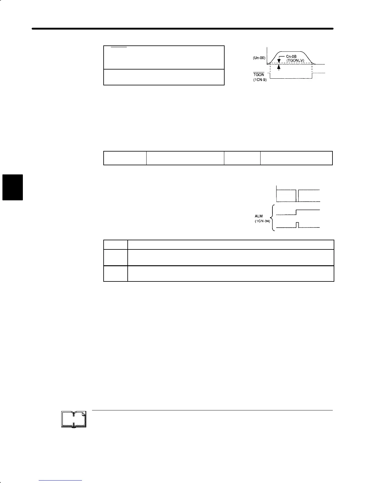
1) Use the following memory switch to specify whether to clear or hold a servo alarm that
occurred at power loss.
Cn-01 Bit 5
Operation to Be Performed at
Recovery from Power Loss
Factory
Setting: 0
For Speed/Torque Control
and Position Control
If the Servopack detects instantaneous voltage
drop in power supply, it outputs alarm A.F3 to pre-
vent a hazardous situation.
Select the operation to be performed when volt-
age is recovered after alarm occurrence.
Setting Meaning
0
Holds servo alarm even after recovery from power loss.
ALM output remains OFF (circuit between 1CN-34 and 1CN-35 remains open).
1
Clears servo alarm after recovery from power loss.
ALM output remains ON (circuit between 1CN-34 and 1CN-35 is closed).
2) If this memory switch is set to “1” (to clear servo alarm), power loss is not stored as alarm
traceback data.
TERMS
Alarm traceback data
The SGDA Servopack stores up to 10 last alarms as alarm data. This alarm data can be
displayed with a Digital Operator. For details, refer to 4.2.1 Operation in Alarm Trace-back
Mode.
3
Motor
speed
200 or
100 V
supply
voltage
Power loss
Cn-01 bit 5 = 0
Cn-01 bit 5 = 1
 Loading...


