BASIC USES OF Σ-SERIES PRODUCTS
2.3.2 Main Circuit Wiring and Power ON Sequence
28
2.3.2 Main Circuit Wiring and Power ON Sequence
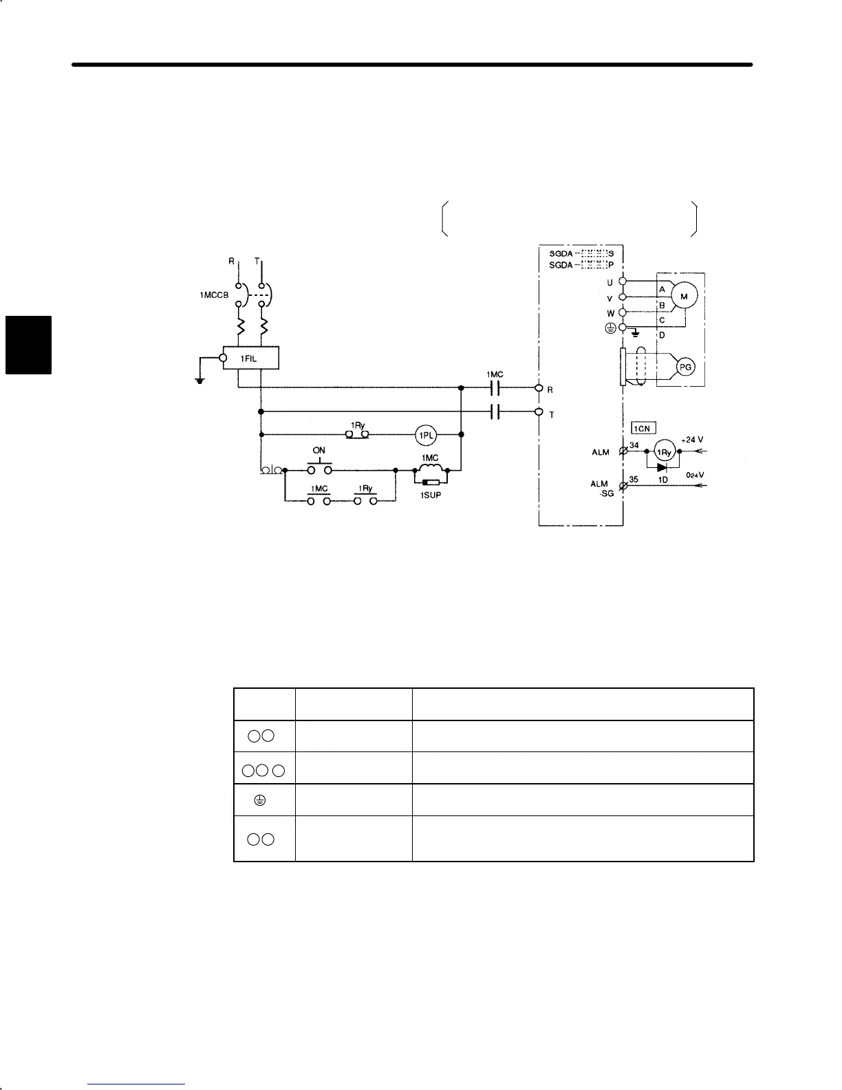
1) The following diagram shows a typical example of wiring the main circuit for Σ-Series
products:
1MCCB: Circuit breaker
1FIL: Noise filter
1MC: Contactor
1Ry: Relay
1PL: Patrol light
1SUP: Surge suppressor
1D: Flywheel diode
For 100 V Type
Single-phase 100 to 115 VAC 50/60 Hz
Single-phase 200 to 230 VAC 50/60 Hz
+ 10
–15
% ,
+ 10
–15
% ,
2) The following table shows the name and description of each main circuit terminal:
Terminal
Symbol
Name Description
RT
Main circuit AC
input terminal
Single-phase 200 to 230 VAC , 50/60Hz
*
+ 10
–15
%
UV W
Motor connection
terminal
Connect U to the red motor terminal , V to the white motor
terminal, and W to the blue motor terminal
Ground terminal
Connect to the motor ground terminal (green) for grounding
purposes.
PN
Regenerative unit
connection
terminal
Connect to a regenerative unit when applicable.
* For 100 V power supply: Single-phase 100 to 115 VAC
+ 10
–15
%
, 50/60Hz
2
 Loading...


