SERVO SELECTION AND DATA SHEETS
5.2.2 Mechanical Characteristics
232
5.2.2 Mechanical Characteristics
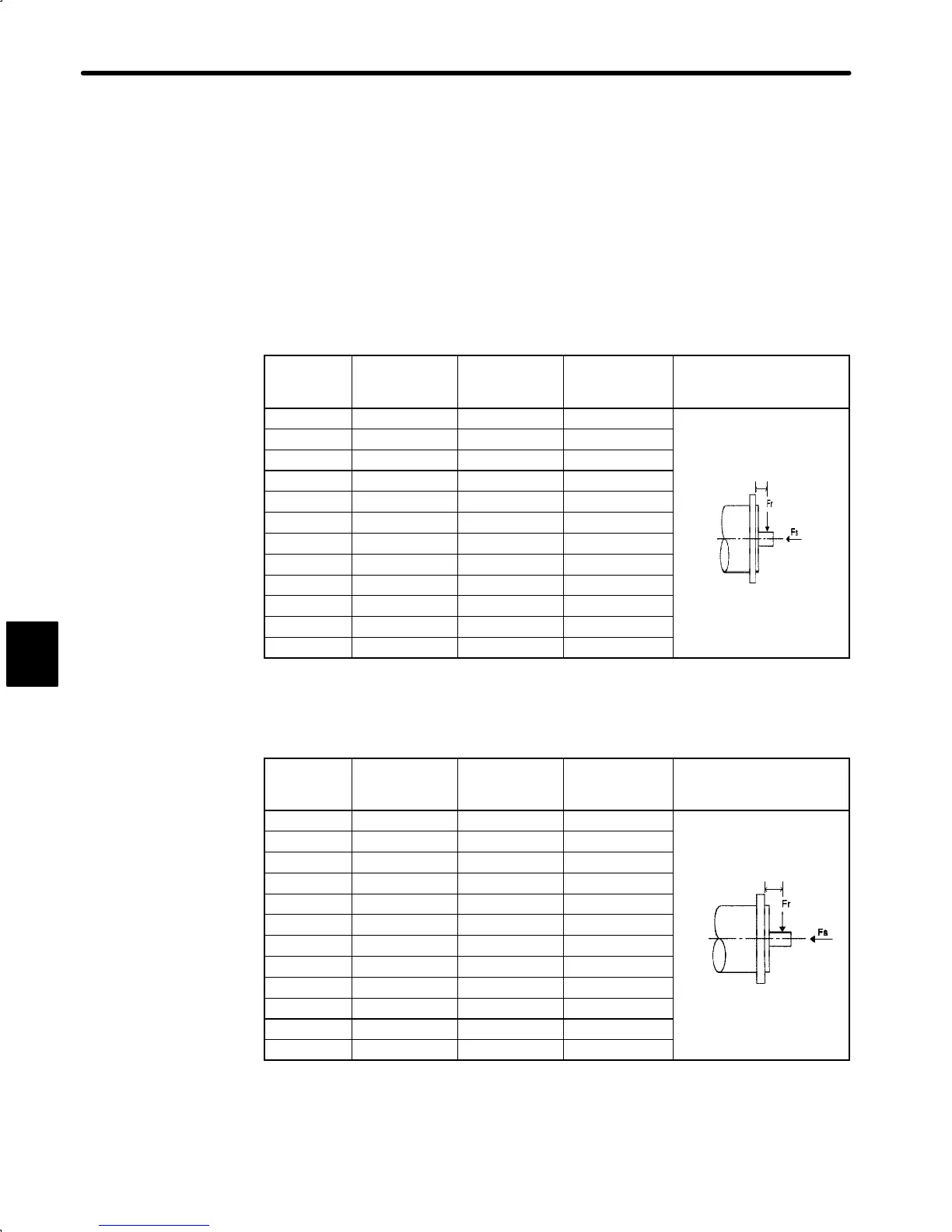
1) Allowable Radial Load, Allowable Thrust Load
The output shaft allowable loads for SGM and SGMP Servomotor are shown below.
Conduct mechanical design such that the thrust loads and radial loads do not exceed the
values stated below.
• Servomotor with incremental encoder
Motor Type
Allowable
Radial Load
Fr [N(lb)]
Allowable
Thrust Load
Fs [N(lb)]
LR
mm
(in.)
Reference Drawing
SGM-A3 68 (15) 54 (12) 20 (0.82)
SGM-A5 68 (15) 54 (12) 20 (0.82)
SGM-01 78 (17) 54 (12) 20 (0.82)
SGM-02 245 (55) 74 (16) 25 (1.02)
LR
SGM-03 245 (55) 74 (16) 25 (1.02)
SGM-04 245 (55) 74 (16) 25 (1.02)
SGM-08 392 (88) 147 (33) 35 (1.43)
SGMP-01 78 (17) 49 (11) 20 (0.82)
SGMP-02 245 (55) 68 (15) 25 (1.02)
SGMP-03 245 (55) 68 (15) 25 (1.02)
SGMP-04 245 (55) 69 (15) 25 (1.02)
SGMP-08 392 (88) 147 (33) 35 (1.43)
• Servomotor with absolute encoder
Motor Type
Allowable
Radial Load
Fr [N(lb)]
Allowable
Thrust Load
Fs [N(lb)]
LR
mm
(in.)
Reference Drawing
SGM-A3 49 (11) 19 (4) 20 (0.82)
SGM-A5 68 (15) 19 (4) 20 (0.82)
SGM-01 68 (15) 19 (4) 20 (0.82)
SGM-02 196 (44) 49 (11) 25 (1.02)
LR
SGM-03 196 (44) 49 (11) 25 (1.02)
SGM-04 196 (44) 68 (15) 25 (1.02)
SGM-08 343 (77) 98 (22) 35 (1.43)
SGMP-01 78 (17) 49 (11) 20 (0.82)
SGMP-02 245 (55) 68 (15) 25 (1.02)
SGMP-03 245 (55) 68 (15) 25 (1.02)
SGMP-04 245 (55) 69 (15) 25 (1.02)
SGMP-08 392 (88) 147 (33) 35 (1.43)
Note The radial load and thrust load limit values are the sum of the loads generated by
the motor torque and the external loads applied to the shaft.
5
 Loading...


