3.7Forming a Protective Sequence
129
NOTE Do not use the S-ON signal to start or stop the motor. Always use an input reference to
start and stop the motor.
2) If the S-ON
signal is not to be used, set the following memory switch to 1:
Cn-01 Bit 0
Use of Servo ON Input Signal Factory
Setting: 0
For Speed/Torque Control
and Position Control
This memory switch is used to enable or disable
the servo ON input signal S-ON
(1CN-14).
When external short-circuit wiring is omitted, set
the memory switch to “1.”
Setting Meaning
0
Uses servo ON signal S-ON.
(When 1CN-14 is open, servo is OFF. When 1CN-14 is at 0 V, servo is ON.)
1 Does not use servo ON signal S-ON.
3.7.3 Using Positioning Complete Signal
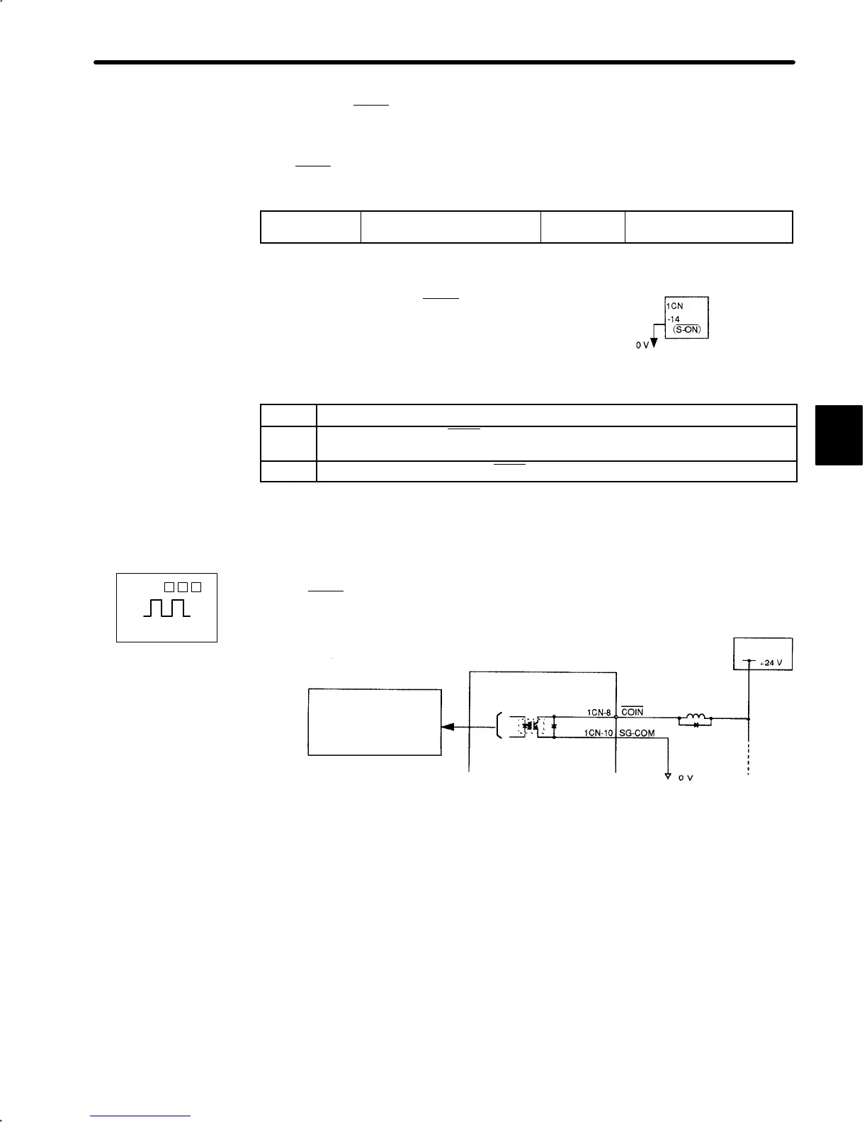
1) This section describes how to wire and use contact output-signal “positioning complete
output (COIN
).” This signal is output to indicate that servomotor operation is complete.
Photocoupler output
Per output:
Maximum operation voltage:
30 VDC
Maximum output current:
50 mADC
Servopack
I/O power
supply
3
Servopack
When S-ON is not used, this short-circuit
wiring can be omitted.
SGDA- P
Positions
 Loading...


