<11. Inspection and Maintenance>
11-2
IM 11M12A01-04E 11th Edition : Jul. 19, 2017-00
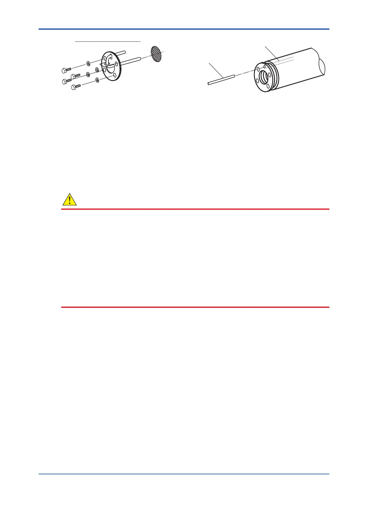
F11.1E.ai
Calibration gas tube
Exploded view of components
Rod
(with outside diameter
of 2 to 2.5 mm)
Figure 11.1 Cleaning the Calibration Gas Tube
11.1.2 Replacing the Sensor Assembly
The performance of the sensor (cell) deteriorates as its surface becomes soiled during operation.
Therefore, you have to replace the sensor when its life expectancy expires, for example, when it
can no longer satisfy a zero correction ratio of 100 ± 30% or a span correction ratio of 0 ± 18%.
In addition, the sensor assembly is to be replaced if it becomes damaged and can no longer
operate during measurement.
If the sensor becomes no longer operable (for example, due to breakage), investigate the cause
and remedy the problem as much as possible to prevent recurrence.
CAUTION
• If the sensor assembly is to be replaced, allow enough time for the detector to cool down
from its high temperature. Otherwise, you may get burned.
• If the cell assembly is to be replaced, be sure to replace the metal O-ring and the contact
together. Additionally, even in a case where the cell is not replaced, if the contact becomes
deformed and cannot make complete contact with the cell, replace the contact.
• If there is any corroded or discolored area in the metal O-ring groove in which the contact
is embedded, sand the groove with sandpaper or use a metal brush, and then sand further
with a higher grade of sandpaper (No. 1500 or so), or use an appropriate metal brush
to eliminate any sharp protrusions on the groove. The contact’s resistance should be
minimized.
• Use cell assemblies manufactured in or after Sept. 2000: the serial number on the side of
the cell assembly should be 0J000 or later (for example: 0K123, 1AA01 etc.)
1. Identifying parts to be replaced
In order not to lose or damage disassembled parts, identify the parts to be replaced from among
all the parts in the sensor assembly. Normally, replace the sensor (cell), metal O-ring and contact
together at the same time. If required, also replace the U-shaped pipe, bolts, lter and associated
spring washers.
2. Removal procedures
(1) Remove the four bolts and associated washers from the tip of the detector probe.
(2) Remove the U-shaped pipe support together with the U-shaped pipe. Remove the lter
also.
(3) Pull the sensor assembly toward you while turning it clockwise. Also, remove the metal
O-ring between the assembly and the probe.
(When replacing the assembly, be careful not to allow any aws on the tip of the probe with
which the metal O-ring comes in contact (the surface with which the sensor ange also
comes in contact. Otherwise, the sample gas will not be sealed.)
(4) Use tweezers to pull the contact out of the groove.

 Loading...


