<2.Specications>
2-18
IM 11M12A01-04E 11th Edition : Jul. 19, 2017-00
Unit: mm
4-Ø6
122
100
Increasing of insertion length
F11-1.ai
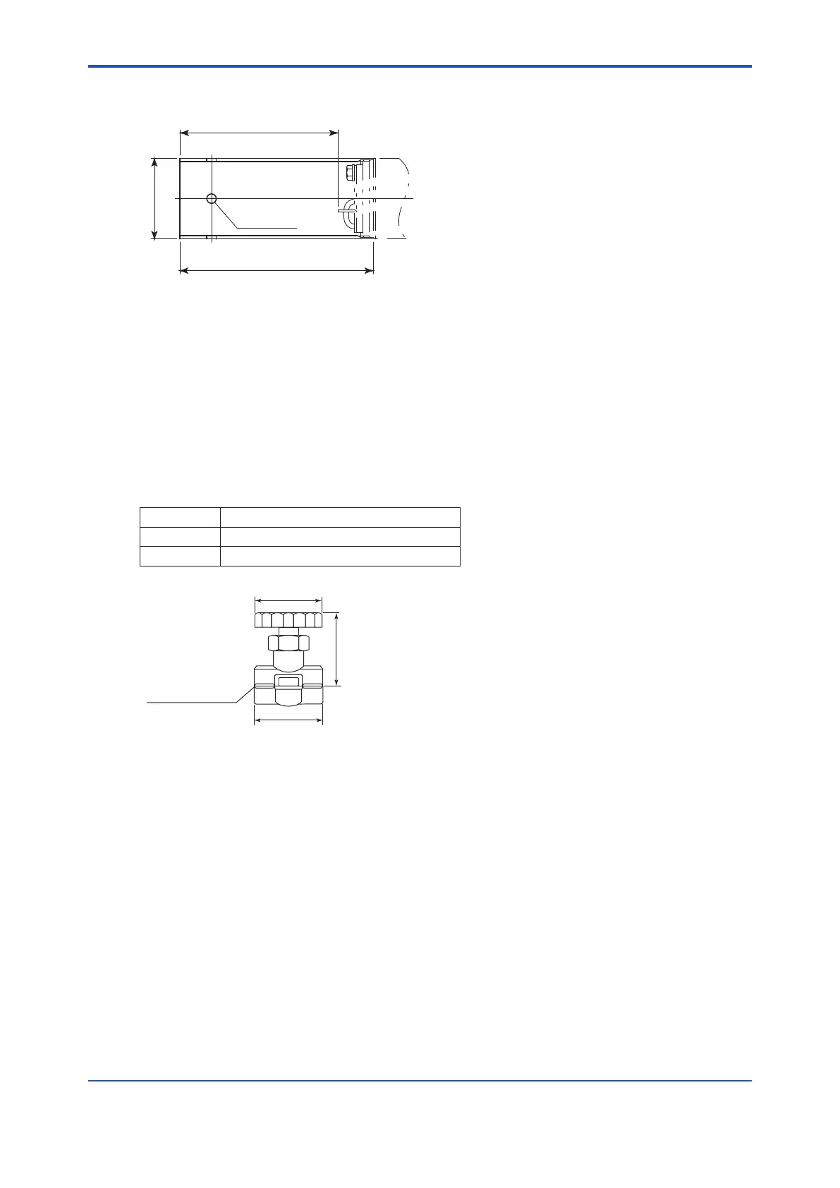
2.4.3 Stop Valve (part no. L9852CB or G7016XH)
This valve is mounted on the calibration gas line in the system to allow for manual calibration.
This is applied to a system conguration (System 1).
Standard Specications
Connection: Rc1/4 or 1/4NPT (Female)
Material: SUS 316 (JIS)
Weight: Approx. 150 g
Part No. Description
L9852CB Joint: Rc1/4, Material: SUS316 (JIS)
G7016XH Joint: 1/4NPT (F), Material: SUS316 (JIS)
F15.ai
58
(Full open length)
40
Rc1/4 or 1/4NPT
Ø48
2.4.4 Check Valve (part no. K9292DN or K9292DS)
This valve is mounted on the calibration gas line (directly connected to the detector). This is
applied to a system based on the system conguration (System 2 and 3).
This valve prevents the sample gas from entering the calibration gas line. Although it functions as
the stop valve, operation is easier as it does not require opening/closing at each calibration.
Screw the check valve into the calibration gas inlet of the detector instead of the stop valve.
l Standard Specications
Connection: Rc1/4 or 1/4NPT (Female)
Material: SUS304 (JIS)
Pressure: Between 70 kPa G or more 350 kPa G or less
Weight: Approx. 90 g

 Loading...


