<11. Inspection and Maintenance>
11-8
IM 11M12A01-04E 11th Edition : Jul. 19, 2017-00
F11.5E.ai
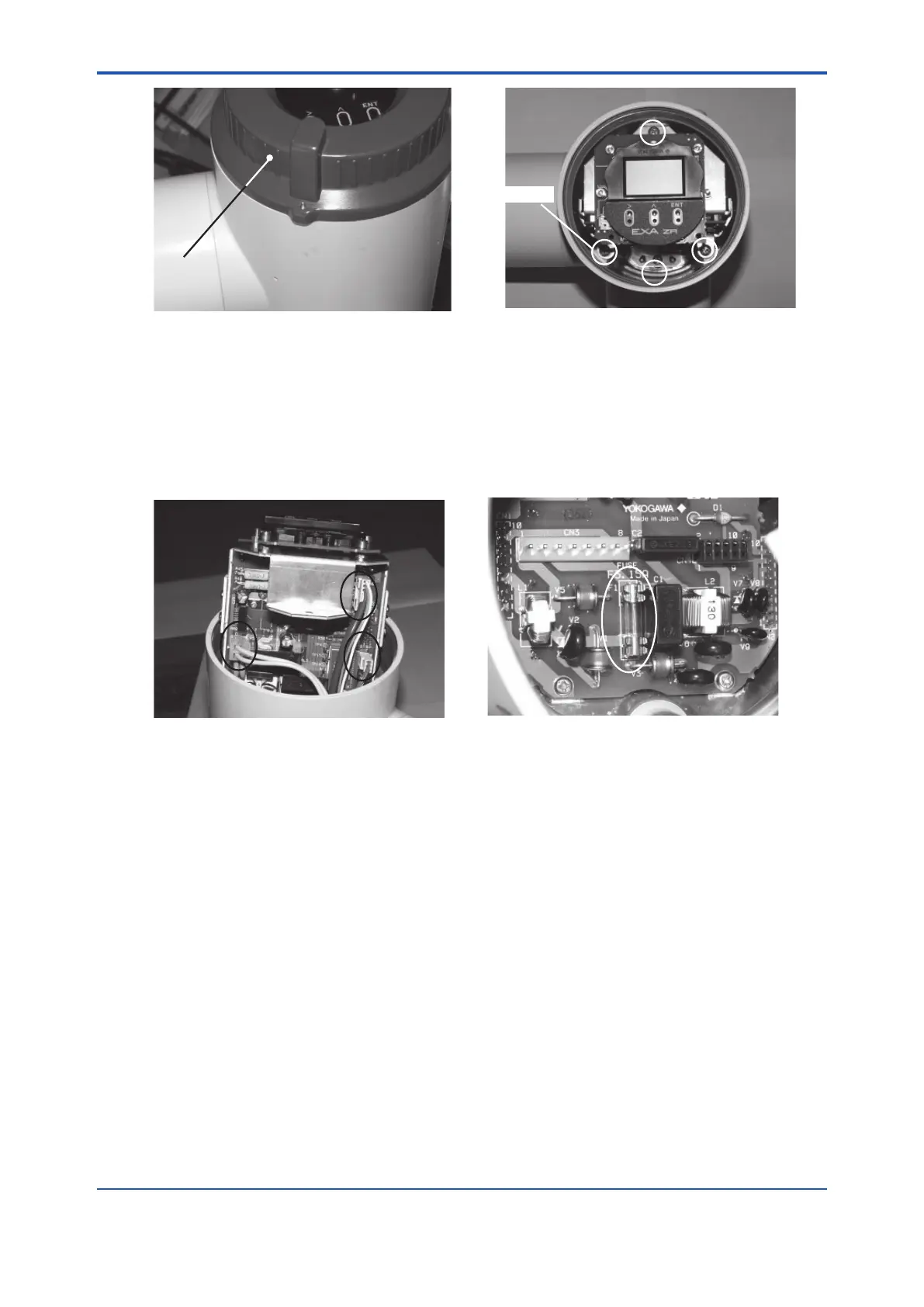
Cover of Display
SCREW
Figure 11.5 Cover of Display Figure 11.6 Location of Screw
(4) Disconnect the three connectors from the printed-circuit board, as shown in Figure 11.7,
by holding the connector housing. Do not pull the leadwire out to remove the connectors,
otherwise, disconnection may result.
(5) Remove the electronics completely to gain access to the fuse on the bottom of the
equipment case (Figure 11.8).
(6) Replace the fuse with a new one.
F11.7E.ai
F11.8E.ai
Figure 11.7 Locations of Connectors Figure 11.8 Location of Fuse
(7) To restore the electronics, reverse the above removal procedures.
When restoring the electronics, do not get leadwire jammed in any part of the unit.
(8) Place the electronics and the printed-circuit board on which the fuse is installed properly;
these are directly connected with connectors.
(9) Tighten the four screws in their positions.
(10) Replace and tighten the display cover properly. If the cover is not tightened sufciently, the
infrared switches will not operate correctly.
n Fuse rating
Check the rating of the fuse and that it satises the following :
Maximum rated voltage : 250 V
Maximum rated current : 3.15 A
Type : Time-lag fuse
Standards : UL-, CSA- and VDE-approved
Part number : A1113EF

 Loading...


