<3. Installation>
3-6
IM 11M12A01-04E 11th Edition : Jul. 19, 2017-00
<Wall Mounting>
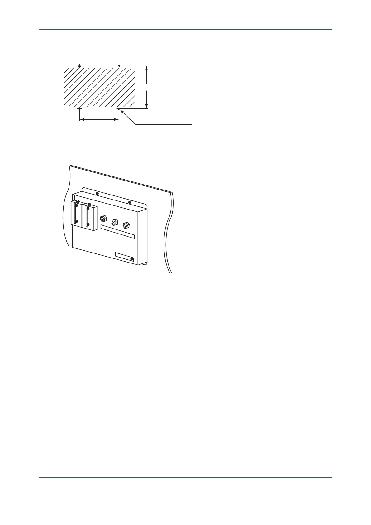
(1) Make a hole in the wall as illustrated in Figure 3.8.
223
140
F3.13E.ai
4 - Ø6 hole, or M5 screw
Figure 3.8 Mounting holes
(2) Mount the ow setting unit. Remove the pipe mounting parts from the mount ttings of the
ow setting unit and attach the unit securely on the wall with four screws.
F3.14E.ai
Figure 3.9 Wall mounting
3.3 Installation of ZR20H Automatic Calibration
Unit
The following should be taken into consideration:
(1) Easy access to the unit for checking and maintenance work.
(2) Near to the detector and the converter
(3) No corrosive gas.
(4) An ambient temperature of not more than 55°C and little change of temperature.
(5) No vibration.
(6) Little exposure to rays of the sun or rain.
n Mounting of ZR20H Automatic Calibration Unit
ZR202G - - - - - A or B is shipped with automatic calibration unit attached.
The automatic calibration unit includes owmeters and solenoid valves, so as to ensure reliable
and accurate operation – Flowmeter should be mounted vertically. The associated probe is
designed for horizontal or vertical mounting.
If you buy the automatic calibration unit afterward, and need to install it or replace it, contact our
service representative.

 Loading...


