<3. Installation>
3-2
IM 11M12A01-04E 11th Edition : Jul. 19, 2017-00
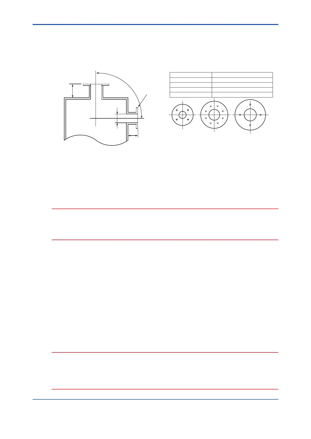
(1) Do not mount the probe with the tip higher than the probe base.
(2) If the probe length is 2.5 m or more, the detector should be mounted vertically (no more than
a 5° tilt).
(3) The detector probe should be mounted at right angles to the sample gas ow or the probe
tip should point downstream.
100 mm
100 mm
F3-1E.ai
(vertical)
Bounds of the probe
insertion hole location
Flange matches
the detector size
(horizontal)
Note
Type
Outside diameter of detector
Standard 50.8 mm in diameter (Note)
With dust filter 51 mm in diameter (Note)
With probe protector
60.5 mm in diameter (Note)
With dust protector
80 mm in diameter or longer (Note)
Four-hole flange Eight-hole flange
*1
*1
JIS flange
(the detector with
dust protector)
(Note) When using the detector with pressure compensation, ensure that the ange gasket does not block the reference gas outlet on
the detector ange. If the ange gasket blocks the outlet, the detector cannot perform pressure compensation.
Where necessary, make a notch in the ange gasket.
When using the detector with ZH21B dust protector the diameter of the hole should be 80mm or larger.
Figure 3.1 Illustrates an example of the probe insertion hole
3.1.2 Installation of the Probe
CAUTION
• The cell (sensor) at the tip of the detector is made of ceramic (zirconia). Do not drop the
detector, as impact will damage it.
• A gasket should be used between the anges to prevent gas leakage. The gasket material
should be heatproof and corrosion-proof, suited to the characteristics of the sample gas.
The following should be taken into consideration when mounting the general-use detector:
<General-use detector>
(1) Make sure that the cell mounting screws (four bolts) at the probe tip are not loose.
If a dust lter (see Section 2.4.1) is used, make sure it is properly attached to the detector.
Refer to Section 3.1.3 for installation of the dust lter.
(2) Where the detector is mounted horizontally, the calibration gas inlet and the reference gas
inlet should face downward.
3.1.3 Installation of the Dust Filter (K9471UA), Dust Guard
Protector (K9471UC) Probe Protector (ZO21R)
<Procedures for installing the dust lter (K9471UA)>
CAUTION
• The dust lter is used to protect the Zirconia sensor from corrosive dust or a high
concentration of dust such as in utility boilers and concrete kilns. If a lter is used in
combustion systems other than these, it may have adverse effects such as response delay.
The combustion conditions should be examined carefully before using a lter.
• The dust lter requires gas ow of 1 m/sec or faster at the front surface of the lter.

 Loading...


