<12. Troubleshooting>
12-2
IM 11M12A01-04E 11th Edition : Jul. 19, 2017-00
12.1.2 Measures to Take When an Error Occurs
n Error-1: Cell Voltage Failure
Error-1 occurs when the cell (sensor) voltage input to the converter falls below -50 mV
(corresponding to about 200% O
2
). The following are considered to be the causes for the cell
voltage falling below -50 mV:
(1) Continuity failure between the cell assembly electrode and the contact
(2) Damage or deterioration of the cell assembly
(3) Improper connection between the sensor and the electronics.
(4) Wiring failure inside the detector
(5) Abnormality in the converter electronics
<Locating the failure and Take measures>
1) Turn off the power to the equipment.
2) Remove the cell assembly from the probe. Check for dirty or corroded sensor parts,
including electrode and contact.
3) If the contact part is normal, the cell assembly may be damaged or deteriorated. Replace the
cell assembly. In this case, be sure to replace the metal O-ring and contact.
4) If Error-1 still occurs, check that the sensor and the electronics are properly connected.
5) Remove the probe to gain access to the two connectors (four connectors for the optional
automatic calibration unit), as indicated in Figure 12.2. Check these connectors are
properly connected.
6) If Error-1 still occurs, the electronics may be defective. Contact your local Yokogawa service
or sales representative.
n Error-2: Heater Temperature Failure
This error occurs if the detector heater temperature does not rise during warm-up, or if the
temperature falls below 730°C or exceeds 780°C after warm-up is completed.
Causes considered for cases where Error-2 occurs independently are shown below.
(1) Faulty heater in the probe (heater wire breakage)
(2) Faulty thermocouple in the probe
(3) Failure in the converter electronics
<Search for cause of failure and Take measures>
(1) Turn off the power to the analyzer.
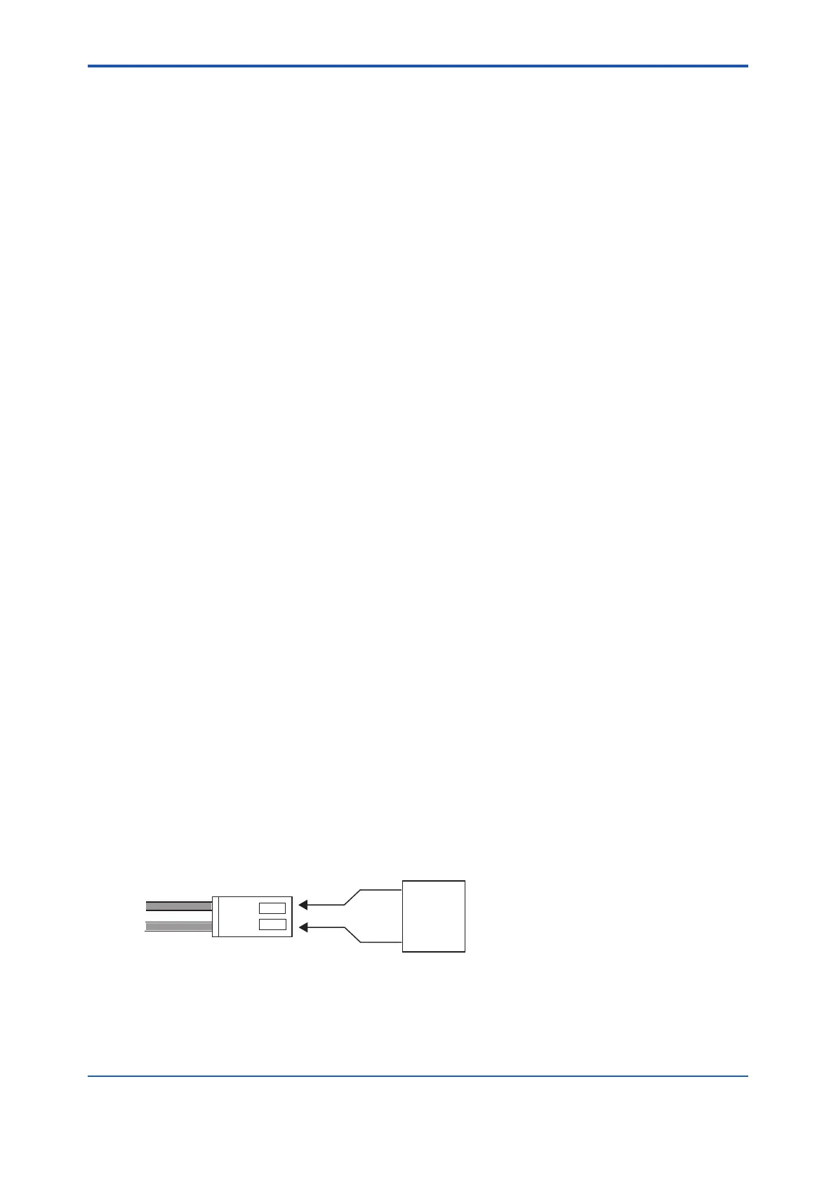
(2) Remove the probe from the analyzer. Also remove all the connectors between the converter
and probe. Measure the resistance of the heater wire (yellow wire) from the probe as
indicated in Figure 12.2. The heater assembly is normal if the resistance is lower than about
90Ω. If the resistance is higher than that value, the heater assembly may be defective. In
this case, replace the heater assembly (refer to Section 11.1.3, “Replacement of the Heater
Assembly”).
F12.2E.ai
Multimeter
(Ω)
Heater wire
Figure 12.2

 Loading...


