<2.Specications>
2-11
IM 11M12A01-04E 11th Edition : Jul. 19, 2017-00
ZH21B.ai
t
C
C
øB
øB
øA
øB
D
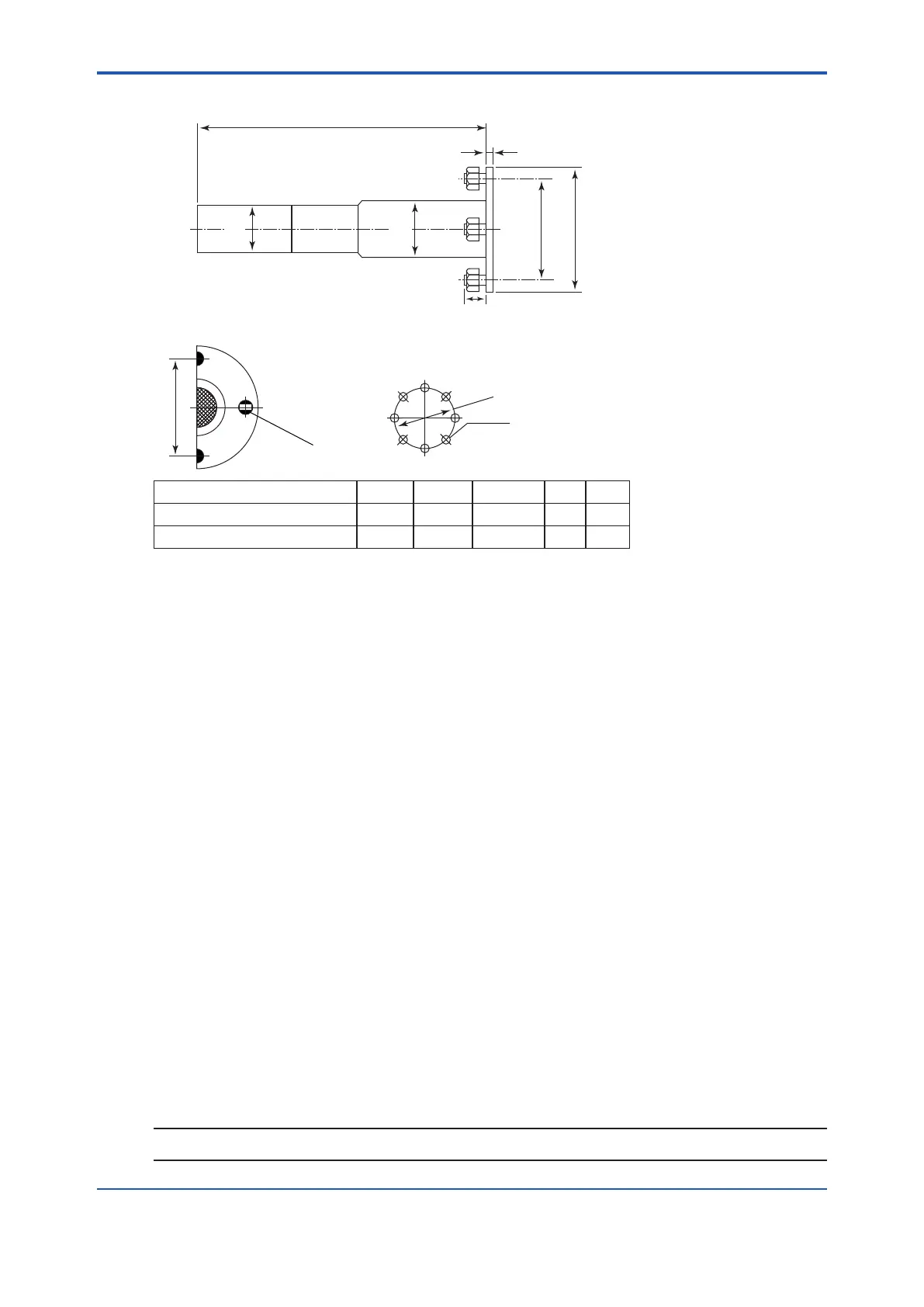
ø72
ø76.3
428 (Insertion length)
Install facing upwards
JIS flange
ANSI flange
Unit: mm
Flange A B C t D
JIS 5K 80 FF 180 145 4 - Ø19 12 40
ANSI Class 150 4B FF 228.6 190.5 8 - Ø19 12 50
2.2 ZA8F Flow Setting Unit and ZR20H
Automatic Calibration Unit
2.2.1 ZA8F Flow Setting Unit
This ow setting unit is applied to the reference gas and the calibration gas in a system
conguration (System 2). Used when instrument air is provided.
This unit consists of a owmeter and ow control valves to control the ow of calibration gas and
reference gas.
Standard Specications
FIowmeter Scale: Calibration gas; 0.1 to 1.0 l/min. Reference gas; 0.1 to 1.0 l/min.
Construction: Dust-proof and rainproof construction
Case Material: SPCC (Cold rolled steel sheet)
Painting: Baked epoxy resin, Dark-green (Munsell 2.0 GY 3.1/0.5 or equivalent)
Tube Connections: Rc1/4 or 1/4NPT (Female)
Reference Gas Pressure:
Clean air supply of sample gas pressure plus approx. 50 kPa G (or
sample gas pressure plus approx.150 kPa when a check valve is used.)
Pressure at inlet of the ow setting unit. (Max. 300 kPa G)
Air Consumption: Approx. 1.5 l/min
Weight: Approx. 2.3 kg
Calibration gas (zero gas, span gas) Consumption: Approx. 0.7 l/min (at calibration time only)
NOTE
Use instrument air for span calibration gas, if no instrument air is available, contact YOKOGAWA.

 Loading...


