<11. Inspection and Maintenance>
11-4
IM 11M12A01-04E 11th Edition : Jul. 19, 2017-00
F11.3E.ai
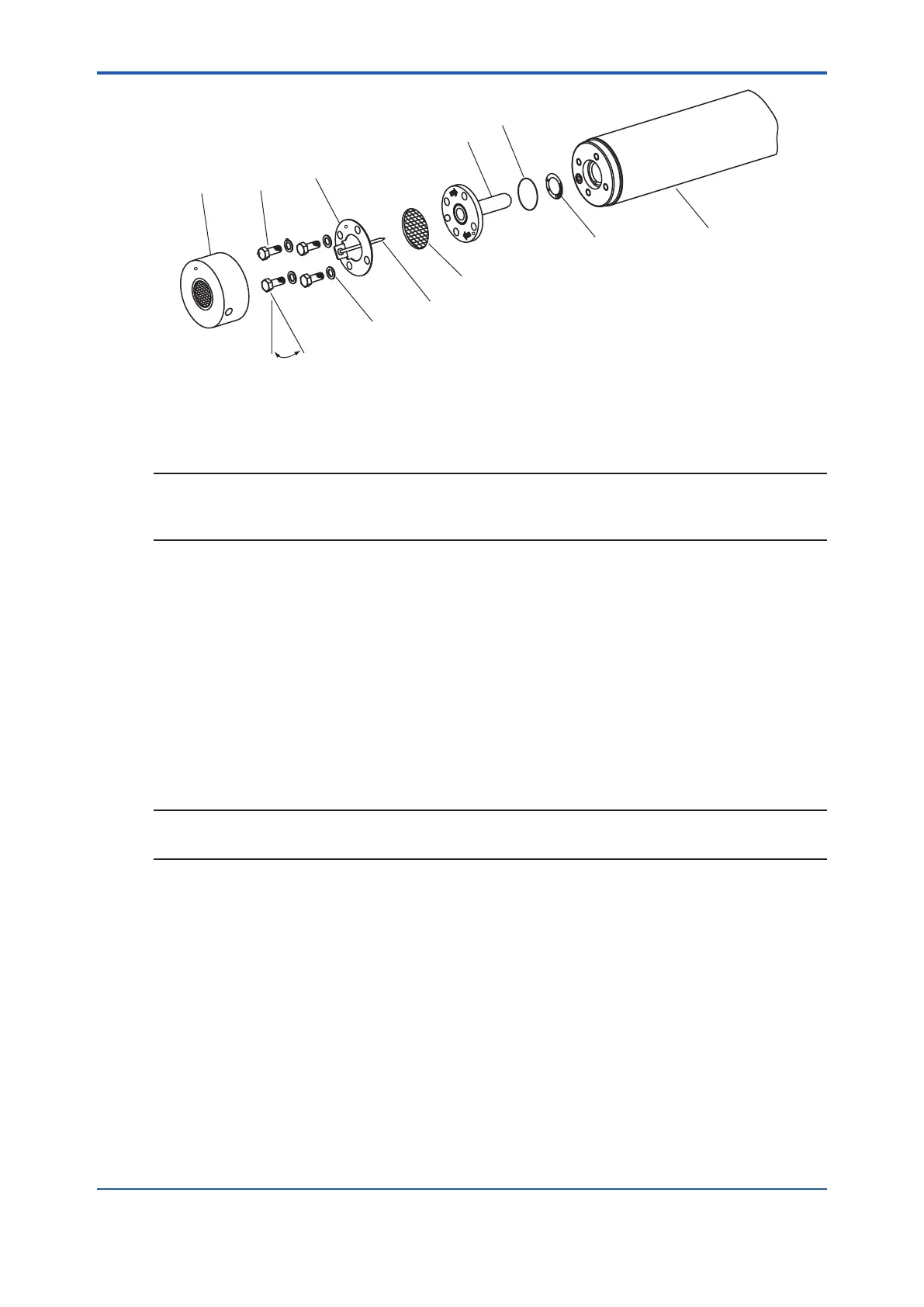
Dust filter
(optional)
Bolts (four)
Washers
(four)
Sensor (cell)
U-shaped pipe
Metal O-ring
Contact
Probe
1/8 turn – tighten bolts 1/8 turn
(approximately 45°) each
U-shaped pipe
support
Filter
Figure 11.3 Exploded View of Sensor Assembly
NOTE
Optional Inconel bolts have a high coefcient of expansion. If excess torque is applied while
the bolts are being tightened, abnormal strain or bolt breakage may result. So, tighten the bolts
following the instructions given above.
11.1.3 Replacement of the Heater Assembly
This section describes the replacement procedure for the heater assembly.
The sensor or ceramic heater-furnace core internal structure is subject to fracturing, so do
NOT subject it to strong vibrations or shock. Additionally, the heater assembly reaches high
temperatures and is subjected to high voltages.
So, maintenance services should be performed after the power is off and the heater assembly
temperature has returned to normal room temperature.
For details, refer to IM 11M12A01-21E “ Heater Assembly “.
NOTE
If the heater assembly can not be removed because a screw for the heater assembly xation has
fused to its thread, one of our service representatives can x it.

 Loading...


