<4. Piping>
4-3
IM 11M12A01-04E 11th Edition : Jul. 19, 2017-00
~
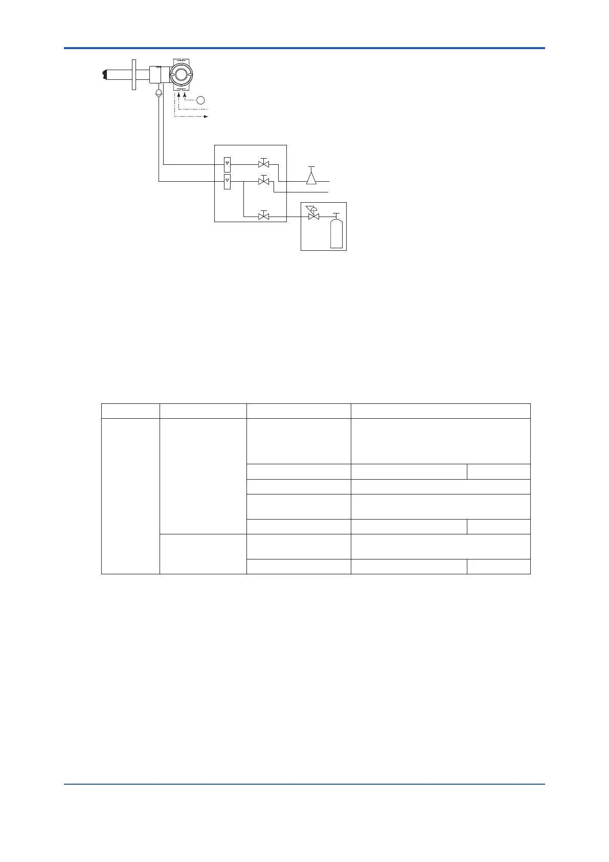
ZR202G Integrated type Zirconia Oxygen/Humidity Analyzer
ZA8F flow setting unit
Reference gas
Calibration gas
Needle
valve
Flowmeter
Instrument air
Air Set
Pressure
regulator
Zero gas cylinder
Calibration gas unit case
Stop valve
or
Check valve
Span gas(Same as Zero gas calibration)
100 to 240 V AC
Contact input
Analog output, contact output
Digital output (HART)
Figure 4.3 Piping for System 2
System 2 illustrated in Figure 4.3 requires piping as follows:
• Mount the check valve or the stop valve through a nipple to the calibration gas inlet of the
equipment.
4.2.1 Piping Parts for System 2
Check that the parts listed in Table 4.2 are provided.
Table 4.2 Piping Parts
Equipment Piping location Parts Name Description
Oxygen/
Humidity
Analyzer
Calibration gas inlet Stop valve or check
valve
Stop valve (L9852CB or G7016XH
recommended by YOKOGAWA
Check valve (K9292DN or K9292DS)
provided by YOKOGAWA
Nipple * Rc1/4 or 1/4 NPT General parts
Zero gas cylinder User' s scope
Pressure Regulator (G7013XF or G7014XF) recommended by
YOKOGAWA
Joint for tube connection Rc1/4 or 1/4 NPT General parts
Reference gas inlet Air set (G7003XF/K9473XK or G7004XF/
K9473XG) recommended by YOKOGAWA
Joint for tube connection Rc1/4 or 1/4 NPT General parts
Note: Parts with marking * are used when required.
General parts can be found on the local market.
4.2.2 Piping for the Calibration Gas
This piping is to be installed between the zero gas cylinder and the ZA8F ow setting unit, and
between the ZA8F ow setting unit and the ZR202G analyzer.
The cylinder should be placed in a case assembly E7044KF or the like to avoid any direct
sunlight or radiant heat so that the gas cylinder temperature may not exceed 40°C.
Mount the pressure regulator (recommended by YOKOGAWA) on the cylinder.
Mount the stop valve or the check valve (recommended by YOKOGAWA) through the nipple
(found on the local market) at the calibration gas inlet of the equipment as illustrated in Figure
4.4. (The stop valve or the check valve may have been mounted on the equipment when
shipped.) Connect the ow setting unit and the analyzer to a 6mm (O.D.) x 4mm (I.D.) (or nominal
size 1/4 inches) or larger stainless steel pipe.

 Loading...


