1 Product Introduction D-Link Smart Managed Switch User Manual
4
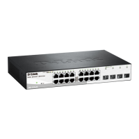
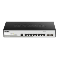
DGS-1210-10P
8-Port 10/100/1000Mbps plus 2 SFP Ports (100/1000Mbps) Smart Managed PoE Switch.
Front Panel
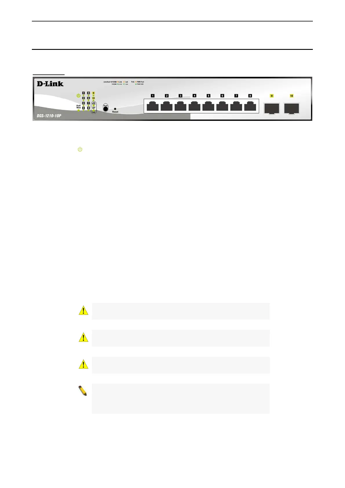
Figure 1.3 – DGS-1210-10P Front Panel
The front panel of the DGS-1210-10P switch consists out of the following:
• Power LED
: The Power LED lights up when the Switch is connected to a power source.
• PoE Max: The PoE Max LED lights up with solid red when the Switch reaches the maximum power
budget defined by the administrator via PoE System Settings page of Web GUI or the default power
budget of 65 Watts.
• Port Link/Act/Speed LED (1-8): The Link/Act/Speed LED flashes, which indicates a network link
through the corresponding port. Blinking indicates that the Switch is either sending or receiving data to
the port. When a port has an amber light, this indicates that the port is running on 10M or 100M. When
it has a green light it is running on 1000M.
• Port Link/Act/Speed LED (9F, 10F): The Link/Act/Speed LED flashes, which indicates a network link
through the corresponding port. Blinking indicates that the Switch is either sending or receiving data to
the port. When the port LED glows in amber, it indicates the port is running on 100M. When the port
LED glows in green, it is running on 1000Mbps.
• LED Mode: To select the mode of port LED, the Link/Act and PoE LED under the mode button will
solid green to indicate which mode is selected.
• Mode: By pressing the Mode button, the Port LED will switch between Link/Act and PoE modes.
• Reset: Press the Reset button for 1~5 seconds to reboot the device. Press the Reset button for 6~10
seconds to reset the Switch back to the default settings and led will be solid light with amber for 2
seconds. Or press the Reset button over 11 seconds to enter the loader mode after device reboot and
the led will be solid light with green for 2 seconds. If the device cannot reboot the Switch via image 1
and image 2, the device will enter the loader mode automatically.
CAUTION: The MiniGBIC ports should use UL
Transceiver product, Rated Laser Class I. 3.3Vdc.
CAUTION: The port 1 ~ port 8 are PoE ports. When user press the
Mode button to PoE mode, only port 1 ~ port 8 will light up.
CAUTION: This equipment can be co
networks without routing to the outside plant.
NOTE: Once user enter in loader mode, you can use DNA tool
(standalone version 2.0.2.4 only (No support by Chrome
DNA3.x.x.x)) to download the image or call D-
Support for further help.
 Loading...