4 Web-based Switch Configuration D-Link Smart Managed Switch User Manual
5
5
5
5
Restricted TCN: Toggle between True and False to set the restricted TCN of the packet. Topology Change
Notification (TCN) is a BPDU that a bridge sends out to its root port to signal a topology change. If set to
True, it stops the port from propagating received TCN and to other ports. The default value is False.
Forwarding BPDU: Bridges use Bridge Protocol Data Units (BPDU) to provide spanning tree information.
STP BPDUs filtering is useful when a bridge interconnects two regions; each region needing a separate
spanning tree. BPDU filtering functions only when STP is disabled either globally or on a single interface.
The possible field values are:
Disabled – BPDU filtering is enabled on the port.
Enabled – BPDU forwarding is enabled on the port (if STP is disabled).
Hello Time: The interval between two transmissions of BPDU packets sent by the Root Bridge to indicate to
all other switches that it is indeed the Root Bridge. The default value is 2.
Click the Apply button to implement changes made. Click Refresh to renew the page.
L2 Functions > Spanning Tree > MST Configuration Identification
The MST Configuration Identification page allows user to configure a MSTI instance on the switch. These
settings will uniquely identify a multiple spanning tree instance set on the switch. The Switch initially
possesses one CIST or Common Internal Spanning Tree of which the user may modify the parameters for
but cannot change the MSTI ID for, and cannot be deleted.
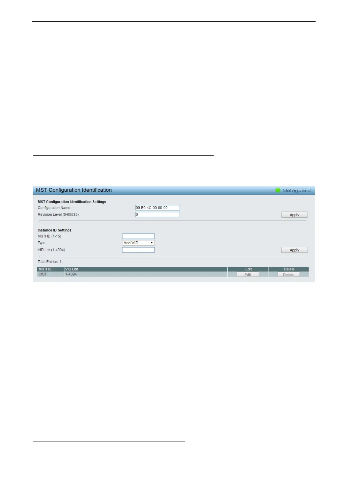
Figure 4.58 – L2 Functions > Spanning Tree > MST Configuration Identification
MST Configuration Identification Settings:
Configuration Name: A previously configured name set on the Switch to uniquely identify the MSTI (Multiple
Spanning Tree Instance). If a configuration name is not set, this field will show the MAC address to the
device running MSTP. This field can be set in the STP Bridge Global Set-tings window.
Revision Level: This value, along with the Configuration Name will identify the MSTP region configured on
the Switch. The user may choose a value between 0 and 65535 with a default setting of 0.
MSTI ID (1-15): Enter a number between 1 and 15 to set a new MSTI on the Switch.
Type: This field allows the user to choose a desired method for altering the MSTI settings.
Add VID - Select this parameter to add VIDs to the MSTI ID, in conjunction with the VID List
parameter.
Remote VID – Select this parameter to remove VIDs from the MSTI ID, in con-junction with the VID
List parameter.
VID List (1-4094): This field displays the VLAN IDs associated with the specific MSTI.
Click Apply to implement changes made.
L2 Functions > Spanning Tree > STP Instance Settings
The STP Instance Settings page display MSTIs currently set on the Switch and allows users to change the
Priority of the MSTPs.
 Loading...