1 Product Introduction D-Link Smart Managed Switch User Manual
1
1
3
3
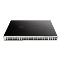
NOTE: On the DGS-1210-52MP, the MiniGBIC ports are shared
with normal RJ-45 ports 49T, 50T, 51T and 52T. When the
MiniGBIC port is used, the RJ-45 port cannot be used.
CAUTION: The MiniGBIC ports should use UL
Transceiver product, Rated Laser Class I. 3.3Vdc.
CAUTION: The port 1 ~ port 48 are PoE ports. When user press
the Mode button to PoE mode, only port 1 ~ port 48 will light up.
CAUTION: This equipment can
networks without routing to the outside plant.
NOTE: Once user enter in loader mode, you can use DNA tool
(standalone version 2.0.2.4 only (No support by Chrome
DNA3.x.x.x)) to download the image or call D-
Support for further help.
Rear Panel
Figure 1.20 – DGS-1210-52MP Rear Panel
Power: Connect the supplied AC power cable to this port.
LED Indicators
The Switch supports LED indicators for Power, Fan, and Link/Act for each port. The following shows the LED
indicators for the DGS-1210 series Smart Managed Switch along with an explanation of each indicator.
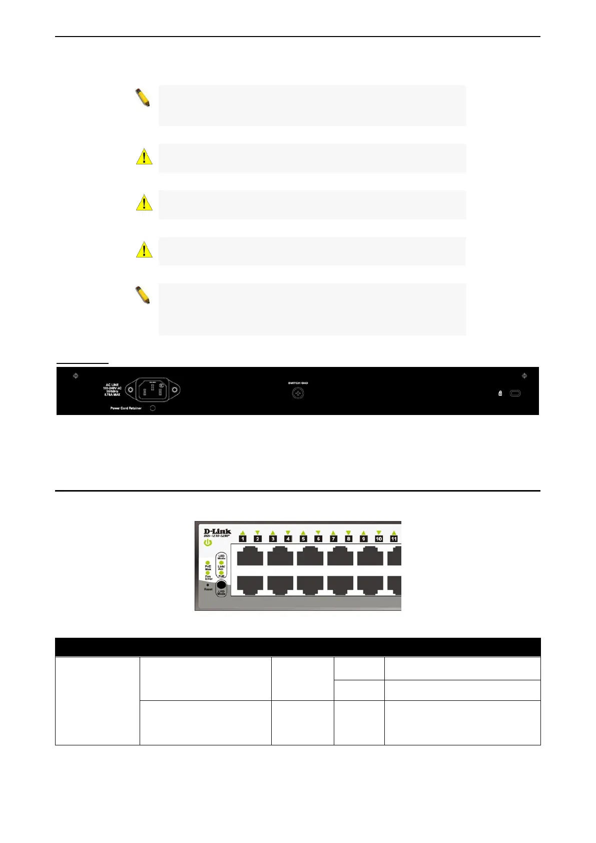
Figure 1.21 –LED Indicators on DGS-1210 series
Location LED Indicative Color Status Description
Per Device
Power
Green
Solid Light
Power on.
Light off Power off.
Fan Error
(For DGS-1210-
28P/28MP/52MP)
Red Solid light
The fan has runtime failure and is
brought offline.
 Loading...