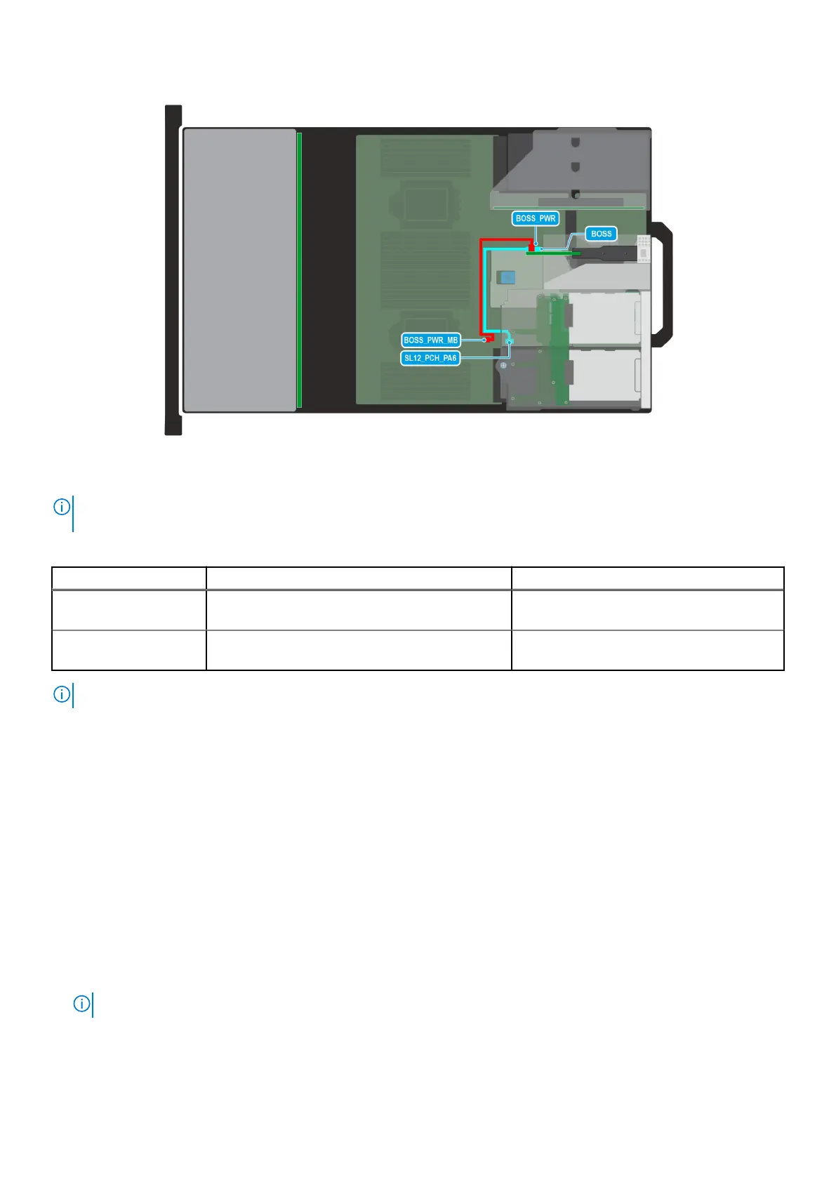
Figure 66. Configuration 43: BOSS-N1 module in 4 x 2.5-inch rear drive module
NOTE:
Follow the sequential order as shown in the table to remove the cables, to install the cables follow the reverse
sequential order.
Table 45. BOSS-N1 module in 4 x 2.5-inch rear drive module
Order From To
1 BOSS_PWR_MB (BOSS power connector on
system board)
BOSS_PWR (BOSS module power
connector)
2 SL12_PCH_PA6 (signal connector on system
board)
BOSS (BOSS module signal connector)
NOTE: The BOSS-N1 signal cable is routed beneath rear drive module and ensure not to damage the cable.
PERC module
This is a service technician replaceable part only.
Removing the rear mounting front PERC module
Prerequisites
1. Follow the safety guidelines listed in the Safety instructions.
2. Follow the procedure listed in the Before working inside your system.
3. Remove the cooling fan cage assembly.
4. Remove the drive backplane cover.
5. If required, remove the air shroud or remove the GPU air shroud..
6. Disconnect all the cables, observe the cable routing.
NOTE: Refer to cable routing section for more information.
Steps
1. Using a Phillips #2 screwdriver, loosen the captive screws on the rear mounting front PERC module.
90
Installing and removing system components
 Loading...