SIRIUS
®
TECHNICAL REFERENCE MANUAL
5.2. Technology overview
Module
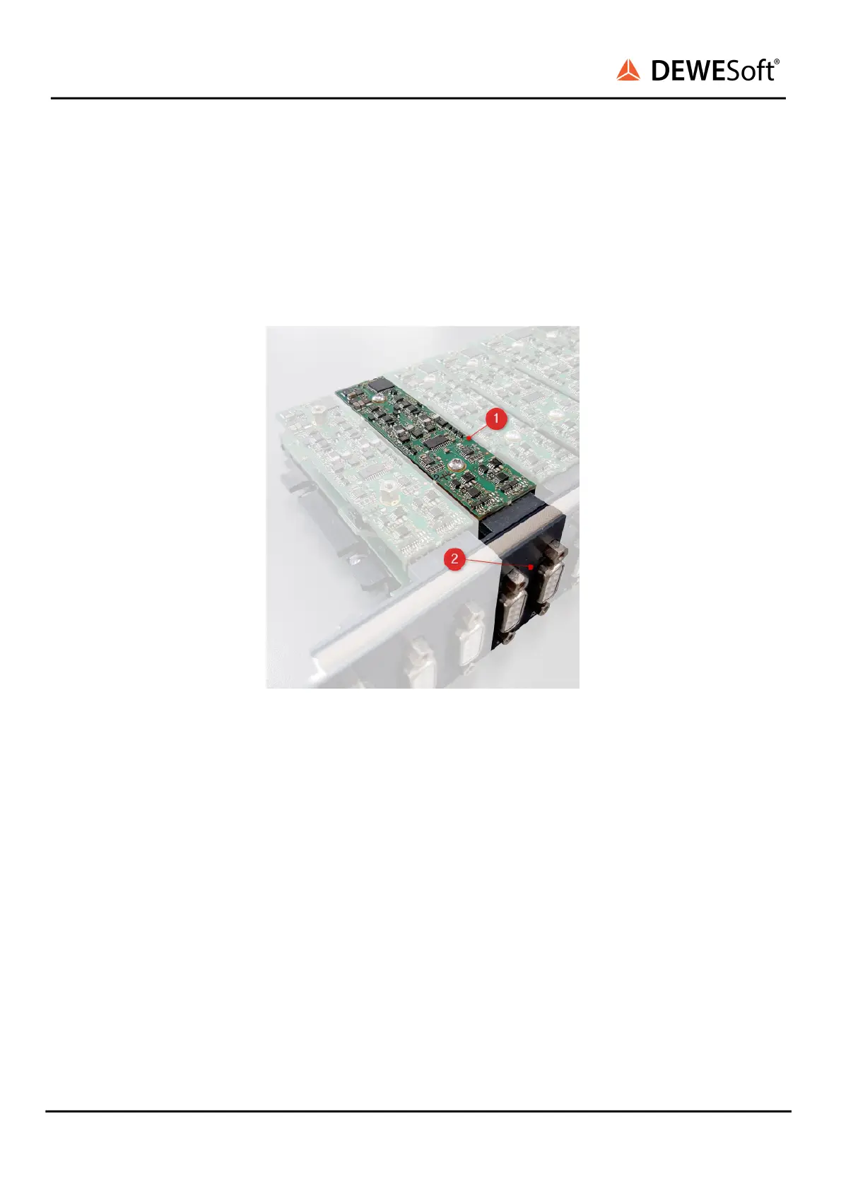
Each SIRIUS® slice can contain up to 8 measurement modules. The illustration below “SIRIUS-HD
module” shows an open SIRIUS® HD measurement slice. The highlighted green PCB ❶ is a single
measurement module. You can see ❷ that this HD slice has 2 connectors (and thus 2 channels) which
are both connected to the same measurement module.
SIRIUS-HD module
The next illustration below “SIRIUS-STGM+ module” shows SIRIUS front with two STG-M+ modules in
different colours. The first module ❶ is surrounded by yellow boxes, the 2nd module ❷ is highlighted
with blue boxes. Each module has a DSUB-9 connector for the analog signals and a LEMO connector for
the digital signals.
Note that the STGM (DSUB-9 female) & CNT (7-pin LEMO female) connectors for the 2 modules share
the common electronic circuit inside. Thus you must always configure these modules as pairs.
SIRIUS
®
V20-1 128 / 336
 Loading...