25Installation and Service Guide: Color Controller E-46A
Installing Hardware
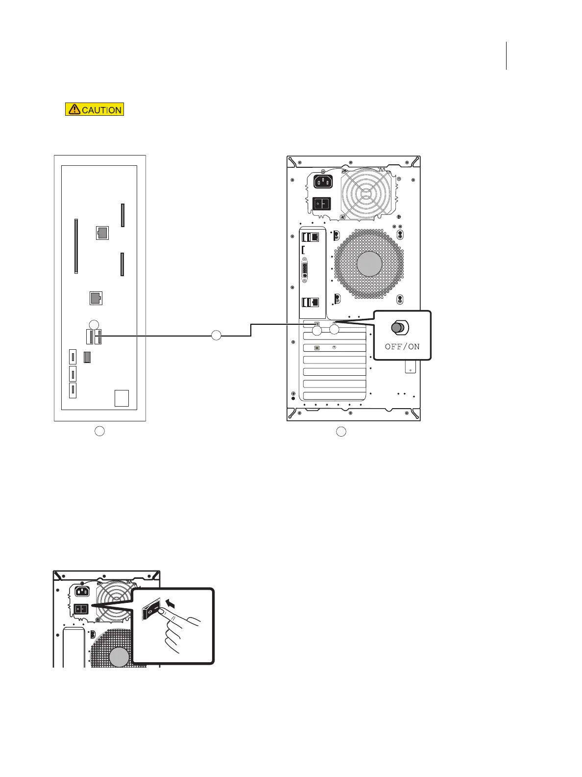
7 Set the power synchronization switch on the E-46A connector panel to ON position.
Figure 8: USB power cable connection between printer and E-46A
8 Make sure that the power switch on the E-46A connector panel is in the ON (|) position.
Figure 9: E-46A power switch
9 Power on the printer.
The E-46A automatically starts up.
Do not change the switch position when the E-46A is powered on.
A Printer connector panel B E-46A connector panel
1 Type A USB port (x2) 3 Type B USB port for power synchronization
2 USB power cable 4 OFF/ON switch for power synchronization
OFF: Left
ON: Right
A
B
4
2
1
3

 Loading...