11.2 Basic information
PWR
BTN
USB1/2
LAN2
LAN1
Channel B, Slot 1 (DIMM-1B)
Channel B, Slot 2 (DIMM-2B)
Channel A, Slot 1 (DIMM-1A)
Channel A, Slot 2 (DIMM-2A)
SERIAL
PWR4
PWR2
PWR1
SATA ODD
USB8
Fan2 (SYS)
Fan1 (SYS)
HDD
LED
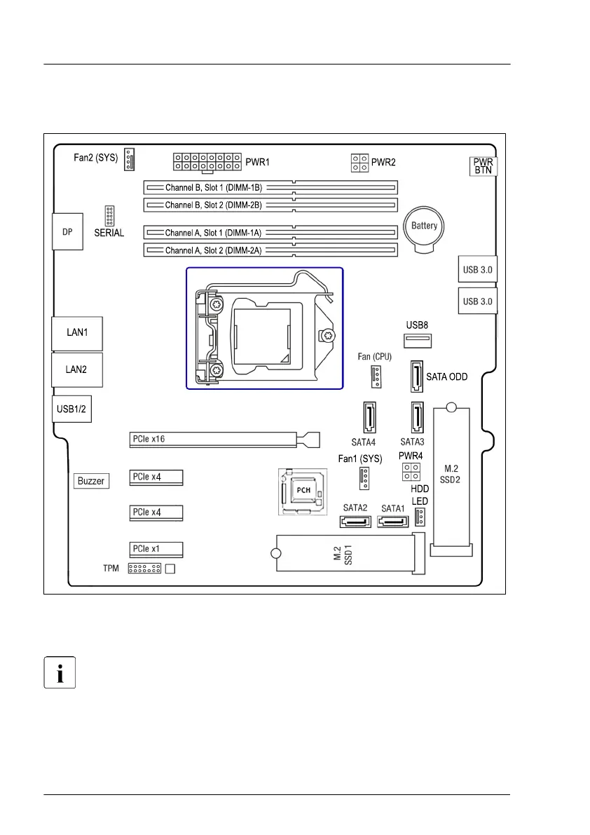
Figure 78: Position CPU socket
The system board supports one CPU socket.
For system relevant information, see the hardware configurator of your
server available online at the following address:
https://ts.fujitsu.com/products/standard_servers/index.htm
For Japan:
https://www
.fujitsu.com/jp/products/computing/servers/primergy/
Processor (CPU)
134 Upgrade and Maintenance Manual TX1310 M5
 Loading...