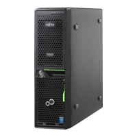
Figure 119: Removing the serial interface (B)
▶
Remove the serial interface (1).
▶
Remove the cable from the system board (2).
Concluding steps
▶
"Reassembling" on page
50
.
▶
"Connecting the power cord" on page 56.
▶
"Switching on the server" on page 57.
▶
"Installing the bay cover" on page 58.
▶
"Locking the server" on page 59.
14.4 Replacing the serial interface
Upgrade and Repair Unit
(URU)
Hardware: 5 minutes
Tools: Hexagon screw driver 5 mm
Serial interface
TX1310 M5 Upgrade and Maintenance Manual 179
 Loading...