CHAPTER 3: INTERFACES FRONT CONTROL PANEL INTERFACE
850 FEEDER PROTECTION SYSTEM – INSTRUCTION MANUAL 3–9
Single Line Diagram BKR1 LED setting for Breaker symbol color configuration
In all 8 Series devices the Breaker symbol color is configurable as per the color scheme
setting in Setpoints > Device > Front Panel > Display Properties > Color Scheme.
Single Line Diagram for 850 and Breaker status color
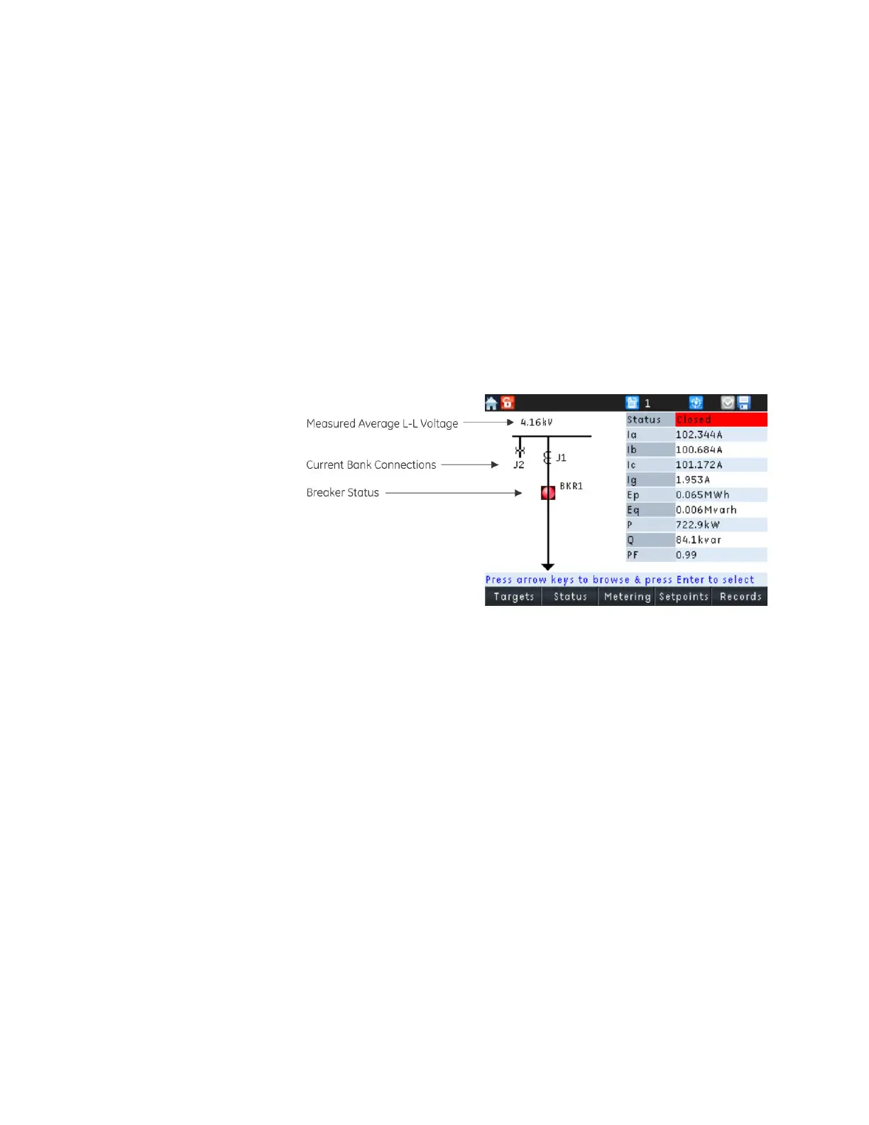
The 850 has a single line diagram (SLD) that represents the power system. The single line
diagram provided is pre-configured to show:
•Breaker status
• AC input connection
•System voltage
Accompanying the single line diagram are typical metered values associated with the
power system.
The single line diagram is configured as the default menu but this can be changed under
Setpoints > Device > Front Panel > Default Screen.
Figure 3-8: SLD and typical metered values screen
The breaker status icon changes state according to the breaker status input and the color
of the icon changes in accordance with the color scheme setting (
Setpoints > Device >
Front Panel > Display Properties > Color Scheme).

 Loading...


