CHAPTER 7: MONITORING FUNCTIONS
850 FEEDER PROTECTION SYSTEM – INSTRUCTION MANUAL 7–17
Functions
Power Factor (55)
It is generally desirable for a system operator to maintain the Power Factor as close to
unity as possible to minimize both costs and voltage excursions. Since the Power Factor is
variable on common non-dedicated circuits, it is advantageous to compensate for low
(lagging) Power Factor values by connecting a capacitor bank to the circuit when required.
The relay allows two stages of capacitance switching for Power Factor compensation.
The relay calculates the average Power Factor in the three phases as follows:
Average Power Factor = Total 3-Phase Real Power / Total 3-Phase Apparent Power
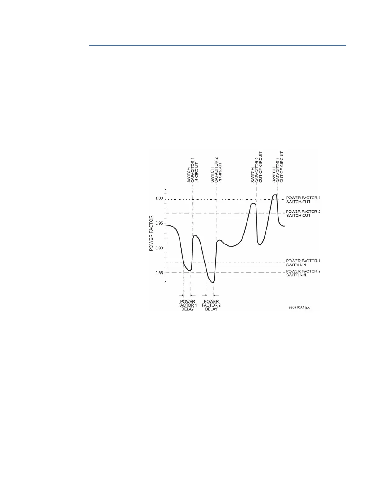
Figure 7-12: Capacitor Bank Switching
When the measured Power Factor becomes more lagging or leading (depending on the
user setting) than the Switch-In level, the relay operates a user-selected output contact.
This output can be used to control a switching device which connects capacitance to the
circuit, or to signal an alarm to the system operator. After entering this state, when the
Power Factor becomes less lagging or leading than the Power Factor Switch-Out level for a
time greater than the set delay, the relay resets the output contact to the non-operated
state.
For delta-connected VTs, the Power Factor feature is inhibited from operating unless all
three voltages are above a threshold and one or more currents are above 0.002 x CT.
Power Factor element delay timers are only allowed to time when the voltage threshold is
exceeded on all phases and the Power Factor remains outside of the region between the
programmed Switch-In and Switch-Out levels. In the same way, when a Power Factor
condition starts the Power Factor delay timer, if all three phase voltages fall below the
threshold before the timer has timed-out, the element resets without operating. A loss of
voltage during any state returns the Power Factor element(s) to the Reset state.
For wye-connected VTs, the power factor value is calculated from the valid phase(s) with a
voltage that is above a user-selected threshold and a current that is above 0.002 x CT.
Power Factor element delay timers are only allowed to time when the supervision

 Loading...


