CHAPTER 7: MONITORING TRANSIENT GROUND FAULT DETECTION
850 FEEDER PROTECTION SYSTEM – INSTRUCTION MANUAL 7–41
Transient Ground Fault Detection
The Transient Ground Fault Detection (TGFD) function, sometimes referred to as Transient
Earth Fault Detection (TEFD), is a technique used to detect the direction of a ground fault in
three different grounding systems: ungrounded, resistance grounded, and compensated/
resonant ground (i.e. Peterson coil grounded). The advantage of an ungrounded or
compensated ground system is that the most common single phase-to-ground fault does
not cause fault current to flow, and therefore the system remains operational, enhancing
network reliability. This operational advantage, however, makes it difficult to detect faults
in these systems, which must be designed to withstand high transient and steady state
overvoltage. Therefore grounded or compensated ground systems are generally only
applied to limited low and medium voltage (LV/MV) distribution systems.
Standard directional techniques used by conventional feeder protection devices are not
adequate for these types of grounded systems. Instead, a novel technique based on the
transient reactive and transient active power principle can be applied, as described in the
following figure for the compensated Peterson coil. The function of the Peterson coil is to
compensate the capacitive current, decreasing the fault arc current, as well as limiting the
voltage of the neutral point, and the recovery voltage of the arc. The Peterson coil
therefore reduces the probability of arc reignition, and at the same time limits the
overvoltage caused by arc reignition.
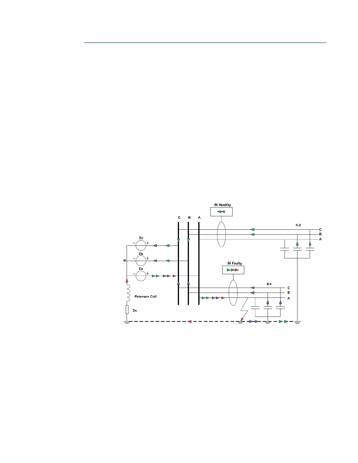
Figure 7-23: TGFD for the compensated Peterson coil
Ground fault detection for Peterson coil grounded systems is difficult due to the small
residual current after compensation. The figure above shows, in the case of a single phase-
to-ground fault occurring on feeder K-1, that the relay on feeder K-1 detects a fault in the
forward direction. However, the relays on other feeders detect the fault in the reverse
direction.
In the Peterson coil figure, the colors represent the following:
• Red: inductive (Peterson coil) current
• Purple: Capacitive (faulty feeder) current
• Green: Capacitive (healthy feeder) current

 Loading...


