CHAPTER 3: INTERFACES FRONT CONTROL PANEL INTERFACE
850 FEEDER PROTECTION SYSTEM – INSTRUCTION MANUAL 3–13
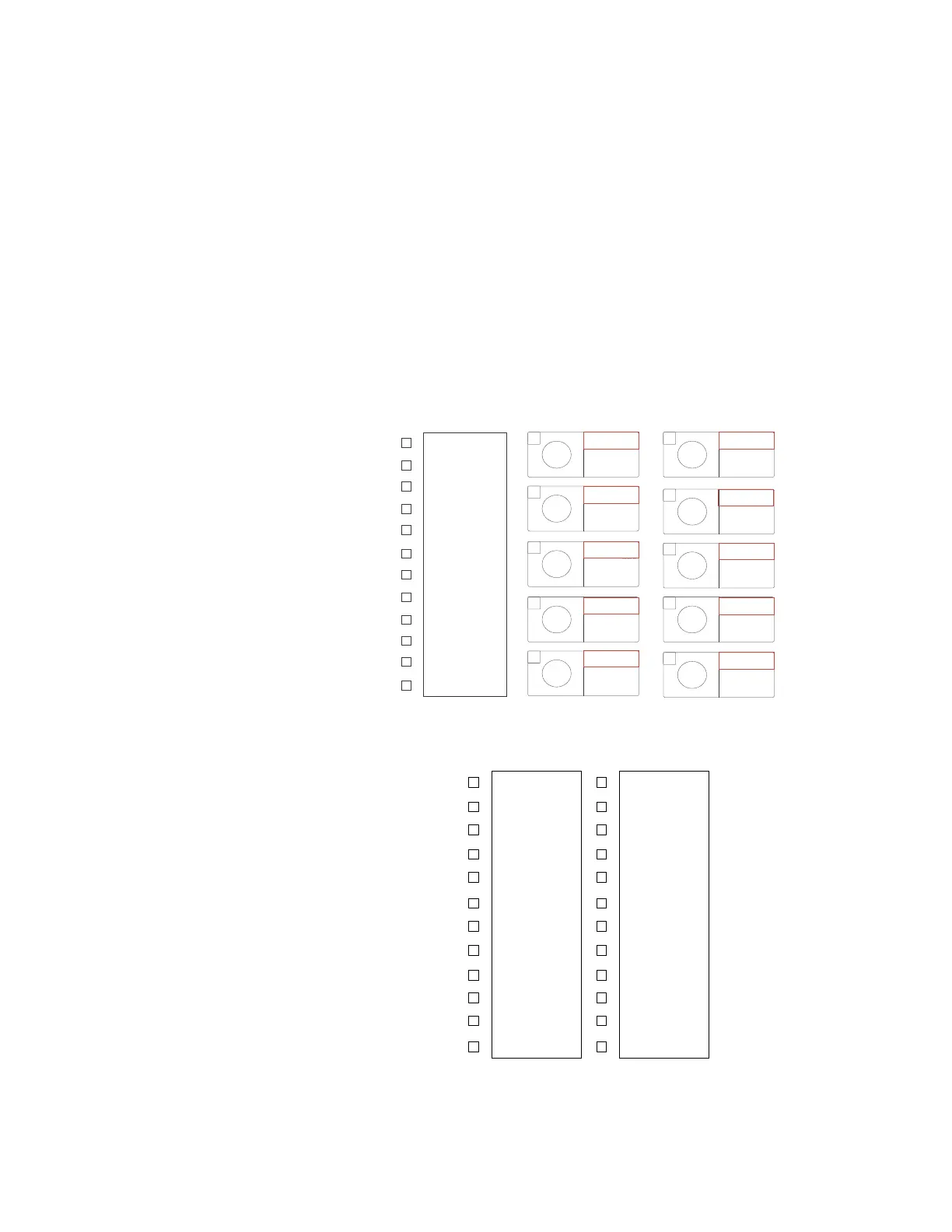
Ten (10) Pushbutton Membrane Front Panel LEDs
Front panel LED details:
• Number of LEDs: 22 (LEDs 13 and 14 are not available)
• Programmability: Any FlexLogic operand
• Reset mode: self-reset or latched
The 8 Series 10 Pushbutton Membrane front panel provides one column of 12 multi-color
LED indicators and 10 single-color LED pushbutton indicators. The “IN-SERVICE” (LED 1) and
the “PICKUP” (LED 4) indicators from the first LED column are non-programmable LEDs. The
indicators “TRIP” (LED 2), and “ALARM” (LED 3) are programmable, and can be triggered by
either a selection of FlexLogic operand assigned in their own menu, or by the operation of
any protection, control or monitoring element with function selected as Trip, Alarm, or
Latched Alarm.
The RESET key is used to reset any latched LED indicator or Target Message once the
condition has been cleared (latched conditions can also be reset via the RESETTING menu).
Figure 3-12: LED numbering
Figure 3-13: Typical LED Indicator Panel
PB
PB
5
7
PB
B
B6
B
PB1
LED 1
LED 2
LED 3
LED 4
LED 5
LED 6
LED 7
LED 8
LED 9
LED 10
LED 11
LED 12
LED 15 LED 16
LED 18
LED 20
LED 17
LED 19
LED 21
LED 23
LED 24
LED 22
LED Labels without
Autoreclose Function
LED Labels with
Autoreclose Function
IN SERVICE
TRIP
ALA RM
PICKUP
TEST MODE
MESSAGE
PHAS E A FAULT
PHAS E B FAULT
PHAS E C FAULT
GROUND FAULT
50P INST OC
27 PHASE UV
IN SERVICE
TRIP
ALA RM
PICKUP
TEST MODE
MESSAGE
PHAS E A FAULT
PHAS E B FAULT
PHAS E C FAULT
GROUND FAULT
50P INST OC
LOCKOUT

 Loading...


