8–36 850 FEEDER PROTECTION SYSTEM – INSTRUCTION MANUAL
SYNCHROCHECK (25) CHAPTER 8: CONTROL
Synchrocheck (25)
The 850 relay provides one Synchrocheck element.
The synchronism check function is intended for supervising the paralleling of two parts of
a system which are to be joined by the closure of a circuit breaker. The Synchrocheck
elements are typically used at locations where the two parts of the system are
interconnected.
If a breaker can be a paralleling point between two generation sources, it is common
practice to automatically perform a check to ensure the sources are within allowable
voltage limits before permitting closing of the breaker. Synchrocheck provides this feature
by checking that the bus and line input voltages are within the programmed differentials of
voltage magnitude, phase angle position, and frequency. If this feature is enabled, the
check will be performed before either manual close or automatic reclose signals can
operate the Close Output Relay. The Synchrocheck programming can allow permitted
closing if either or both of the sources are de-energized.
Synchrocheck verifies that the voltages (BUS and LINE) on the two sides of the supervised
circuit breaker are within set limits of magnitude, angle and frequency difference. The time
during which the two voltages remain within the admissible angle difference is determined
by the setting of the phase angle difference ∆Φ (without angle compensation) and the
frequency difference ∆F (slip frequency). It can be defined as the time it would take the
voltage phasor, BUS or LINE, to traverse an angle equal to 2 × ∆Φ at a frequency equal to
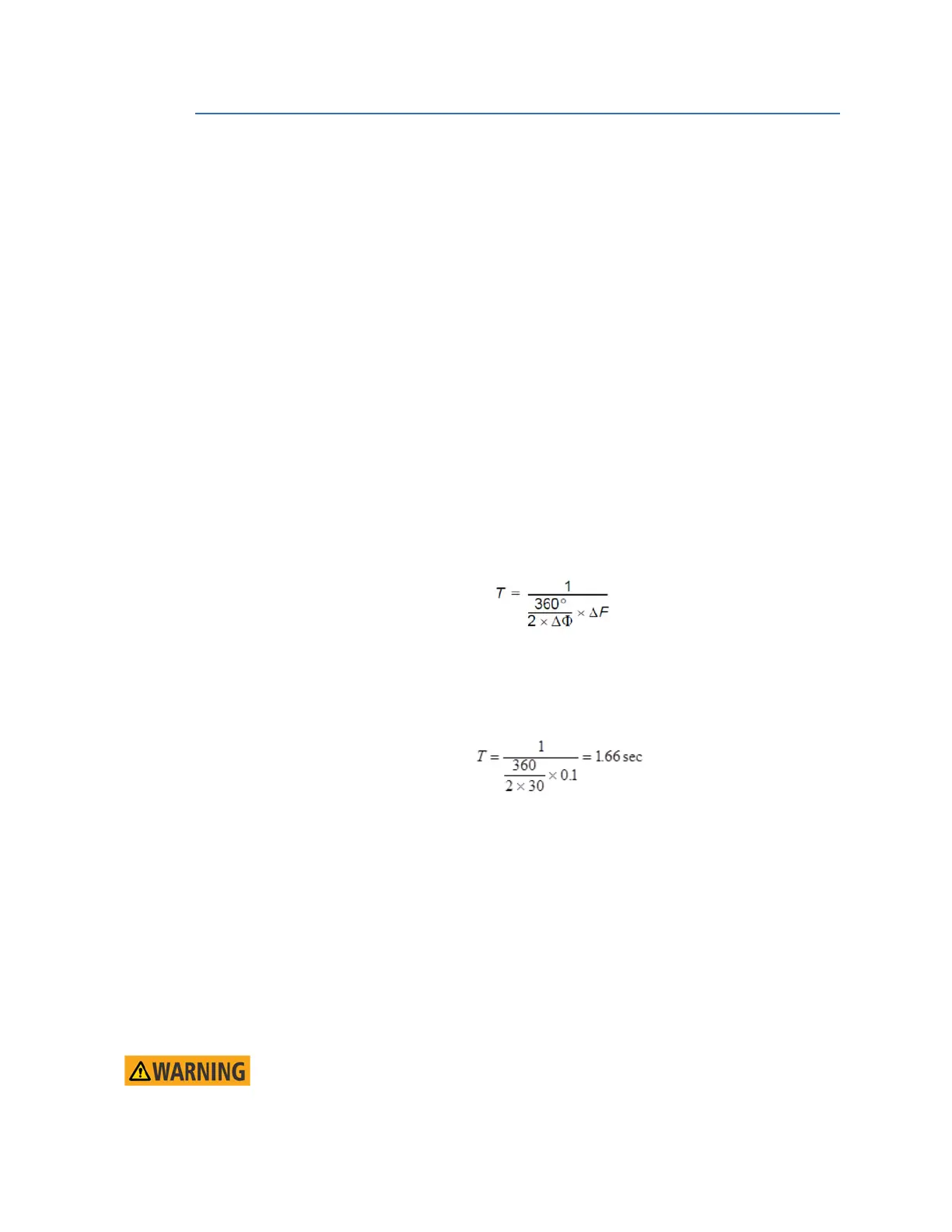
the frequency difference ∆F. This time can be calculated by:
where: ∆Φ = phase angle difference in degrees; ∆F = frequency difference in Hz.
Example:
For the values of ∆Φ = 30° and ∆F = 0.1 Hz, the time during which the angle between the
two voltages is less than the set value is:
As a result the breaker closing time must be less than this computed time, to successfully
close and connect both energized sides.
If one or both sides of the synchronizing breaker are de-energized, the Synchrocheck
programming can allow for closing of the circuit breaker using undervoltage control to by-
pass the Synchrocheck measurements (dead source function).
The measured bus and line input voltage magnitudes, angles and frequencies, and
calculated differential values of angle magnitude and frequency are available as actual
values under METERING / SYNCHROCHECK 1.
The selection of “Aux VT Connection” under Setpoints > System > Voltage Sensing
determines the voltage used for synchrocheck as derived from the three-phase voltages
available on the relay. For example, if the Aux VT Connection is selected as Vab, and the
three-phase VTs are connected in “Wye”, the relay computes delta voltage Vab as well, and
uses it for Synchrocheck.
IMPORTANT:
The Synchrocheck cannot be performed if the three-phase VTs are Delta connected,
and the Wye single voltage input is selected under “Aux VT connection”. “Wye”
voltages cannot be calculated from Delta connected VTs.

 Loading...


