2–14 850 FEEDER PROTECTION SYSTEM – INSTRUCTION MANUAL
ELECTRICAL INSTALLATION CHAPTER 2: INSTALLATION
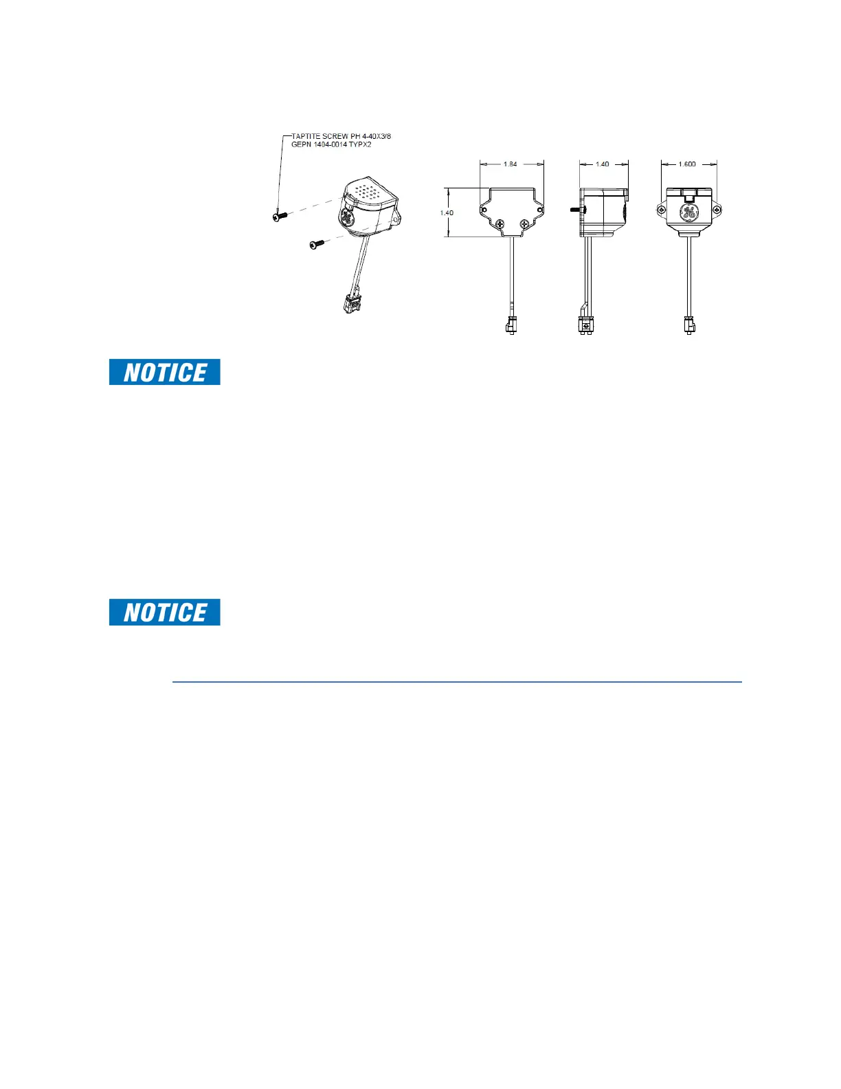
Sensor Installation Figure 2-17: AF Sensor - front, side and top view
FAST PATH:
Review the sensor fiber handling guidelines above.
Sensor fiber should be held in place loosely for the best long-term performance. Avoid
over-tightening ties which may deform or break the sensor fiber.
Before installing the AF sensor unit, ensure that all other drilling and installation is
complete to minimize possible damage to the sensitive unit.
To install the AF sensor and route the sensor fiber, follow these steps:
1. Choose a location for the sensor clear of any obstructions that could shield the sensor
from arc flash light.
2. Mount the sensor securely, using the mounting screw holes.
3. Once the sensor is securely mounted, carefully route the sensor fiber from the AFS
sensor to the base unit, minimizing loops and curves for the strongest possible signal.
4. Secure all sensor fibers (loosely but securely) away from any moving parts.
FAST PATH:
Both the AF sensor connections (CH 1 through CH 4) and the sensor cables are shipped
with dust caps in place to avoid dust contamination. The small rubber dust caps must
be removed before operation.
Electrical Installation
Typical Wiring Diagram
The following illustrates the electrical wiring of the Draw-out unit.

 Loading...


