3.1.15 Motor Bearing Currents
All motors installed with drives 90kW or higher power drives should have NDE (Non-Drive End) insulated bearings installed to eliminate circulating bearing currents.
To minimize DE (Drive End) bearing and shaft currents proper grounding of the drive, motor, driven machine, and motor to the driven machine is required.
Standard Mitigation Strategies:
1. Use an insulated bearing
2. Apply rigorous installation procedures
- Ensure the motor and load motor are aligned
- Strictly follow the EMC Installation guideline
- Reinforce the PE so the high frequency impedance is lower in the PE than the input power leads
- Provide a good high frequency connection between the motor and the frequency converter for instance by screened cable which has a 360°
connection in the motor and the frequency converter
- Make sure that the impedance from frequency converter to building ground is lower that the grounding impedance of the machine. This can
be difficult for pumps
- Make a direct earth connection between the motor and load motor
3. Lower the IGBT switching frequency
4. Modify the inverter waveform, 60° AVM vs. SFAVM
5. Install a shaft grounding system or use an isolating coupling
6. Apply conductive lubrication
7. Use minimum speed settings if possible
8. Try to ensure the line voltage is balanced to ground. This can be difficult for IT, TT, TN-CS or Grounded leg systems
9. Use a dU/dt or sinus filter
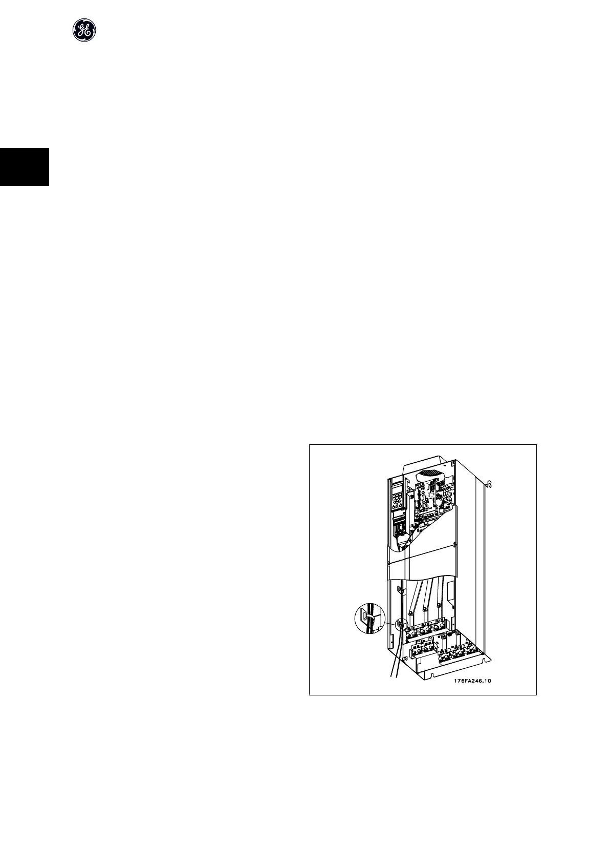
3.1.16 Control cable routing
Tie down all control wires to the designated control cable routing as shown
in the picture. Remember to connect the shields in a proper way to ensure
optimum electrical immunity.
Field Installed Network Module options connection
Connections are made to the network options on the control card. For details
see the relevant network instructions. The cable must be placed to the left
inside the frequency converter and tied down together with other control
wires (see picture).
Illustration 3.16: Wire path for control wiring.
AF-600 FP High Power Operating Instructions
26
3
 Loading...


