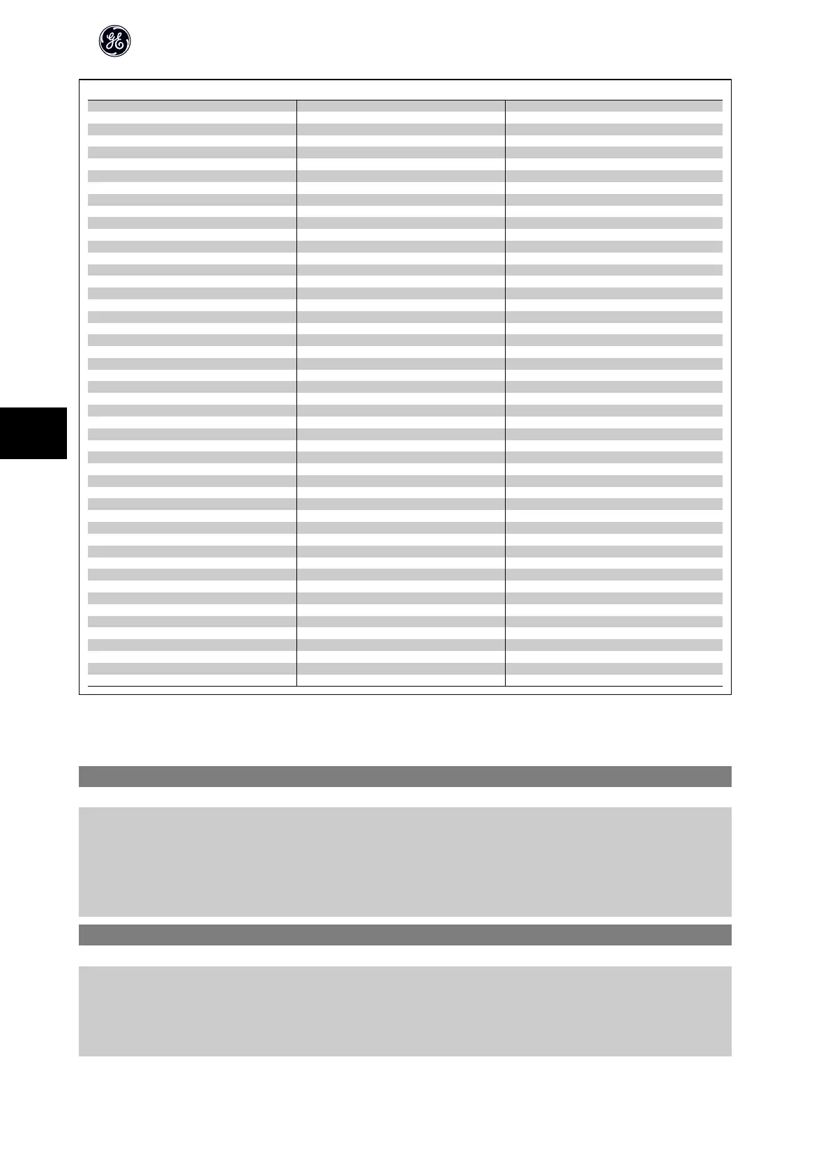
Closed Loop Settings
Single Zone Int. Set Point Single Zone Ext. Set Point Multi Zone / Adv
par. H-40 Configuration Mode par. H-40 Configuration Mode par. H-40 Configuration Mode
par. CL-12 Reference/Feedback Unit par. CL-12 Reference/Feedback Unit par. F-01 Frequency Setting 1
par. CL-13 Minimum Reference/Feedb. par. CL-13 Minimum Reference/Feedb. par. C-30 Frequency Command 2
par. CL-14 Maximum Reference/Feedb. par. CL-14 Maximum Reference/Feedb. par. CL-00 Feedback 1 Source
par. AN-22 Terminal 54 Low Current par. AN-10 Terminal 53 Low Voltage par. CL-01 Feedback 1 Conversion
par. AN-24 Terminal 54 Low Ref./Feedb. Value par. AN-11 Terminal 53 High Voltage par. CL-02 Feedback 1 Source Unit
par. AN-25 Terminal 54 High Ref./Feedb. Value par. AN-12 Terminal 53 Low Current par. CL-03 Feedback 2 Source
par. AN-26 Terminal 54 Filter Time Constant par. AN-13 Terminal 53 High Current par. CL-04 Feedback 2 Conversion
par. AN-27 Terminal 54 Live Zero par. AN-14 Terminal 53 Low Ref./Feedb. Value par. CL-05 Feedback 2 Source Unit
par. AN-00 Live Zero Timeout Time par. AN-15 Terminal 53 High Ref./Feedb. Value par. CL-06 Feedback 3 Source
par. AN-01 Live Zero Timeout Function par. AN-22 Terminal 54 Low Current par. CL-07 Feedback 3 Conversion
par. CL-21 Setpoint 1 par. AN-24 Terminal 54 Low Ref./Feedb. Value par. CL-08 Feedback 3 Source Unit
par. CL-81 PID Normal/ Inverse Control par. AN-25 Terminal 54 High Ref./Feedb. Value par. CL-12 Reference/Feedback Unit
par. CL-82 PID Start Speed [RPM] par. AN-26 Terminal 54 Filter Time Constant par. CL-13 Minimum Reference/Feedb.
par. CL-83 PID Start Speed [Hz] par. AN-27 Terminal 54 Live Zero par. CL-14 Maximum Reference/Feedb.
par. CL-93 PID Proportional Gain par. AN-00 Live Zero Timeout Time par. AN-10 Terminal 53 Low Voltage
par. CL-94 PID Integral Time par. AN-01 Live Zero Timeout Function par. AN-11 Terminal 53 High Voltage
par. CL-81 PID Normal/ Inverse Control par. AN-12 Terminal 53 Low Current
par. CL-82 PID Start Speed [RPM] par. AN-13 Terminal 53 High Current
par. CL-83 PID Start Speed [Hz] par. AN-14 Terminal 53 Low Ref./Feedb. Value
par. CL-93 PID Proportional Gain par. AN-15 Terminal 53 High Ref./Feedb. Value
par. CL-94 PID Integral Time par. AN-16 Terminal 53 Filter Time Constant
par. AN-17 Terminal 53 Live Zero
par. AN-20 Terminal 54 Low Voltage
par. AN-21 Terminal 54 High Voltage
par. AN-22 Terminal 54 Low Current
par. AN-23 Terminal 54 High Current
par. AN-24 Terminal 54 Low Ref./Feedb. Value
par. AN-25 Terminal 54 High Ref./Feedb. Value
par. AN-26 Terminal 54 Filter Time Constant
par. AN-27 Terminal 54 Live Zero
par. AN-00 Live Zero Timeout Time
par. AN-01 Live Zero Timeout Function
par. H-76 Warning Feedback Low
par. H-77 Warning Feedback High
par. CL-20 Feedback Function
par. CL-21 Setpoint 1
par. CL-22 Setpoint 2
par. CL-81 PID Normal/ Inverse Control
par. CL-82 PID Start Speed [RPM]
par. CL-83 PID Start Speed [Hz]
par. CL-93 PID Proportional Gain
par. CL-94 PID Integral Time
par. CL-70 Closed Loop Type
par. CL-71 PID Performance
par. CL-72 PID Output Change
par. CL-73 Minimum Feedback Level
par. CL-74 Maximum Feedback Level
par. CL-79 PID Autotuning
See also AF-600 FP Programming Guide for a detailed description of the Quick Menu parameter groups.
AN-00 Live Zero Timeout Time
Range: Function:
10 s* [1 - 99 s] Enter the Live Zero Time-out time period. Live Zero Time-out Time is active for analog inputs, i.e. terminal
53 or terminal 54, allocated to current and used as reference or feedback sources. If the reference signal
value associated with the selected current input falls below 50% of the value set in par. AN-10 Terminal
53 Low Voltage, par. AN-12 Terminal 53 Low Current, par. AN-20 Terminal 54 Low Voltage or par.
AN-22 Terminal 54 Low Current for a time period longer than the time set in par. AN-00 Live Zero Timeout
Time, the function selected in par. AN-01 Live Zero Timeout Function will be activated.
AN-01 Live Zero Timeout Function
Option: Function:
Select the time-out function. The function set in par. AN-01 Live Zero Timeout Function will be activated
if the input signal on terminal 53 or 54 is below 50% of the value in par. AN-10 Terminal 53 Low Voltage,
par. AN-12 Terminal 53 Low Current, par. AN-20 Terminal 54 Low Voltage or par. AN-22 Terminal 54 Low
Current for a time period defined in par. AN-00 Live Zero Timeout Time. If several time-outs occur simul-
taneously, the frequency converter prioritises the time-out functions as follows:
AF-600 FP High Power Operating Instructions
90
7
 Loading...


