NB!
External stop signals activated by means of control signals or a serial bus will override a “start” command via the Keypad.
[Off]
The [Off] key stops the connected motor. The key can be selected as Enable [1] or Disable [0] via par. K-41 [Off] Button on Keypad. If no external stop function is
selected and the [Off] key is inactive the motor can only be stopped by disconnecting the mains supply.
[Auto ]
The [Auto ] key enables the frequency converter to be controlled via the control terminals and/or serial communication. When a start signal is applied on the
control terminals and/or the bus, the frequency converter will start. The key can be selected as Enable [1] or Disable [0] via par. K-42 [Auto] Button on Keypad.
[Reset]
The [Reset] key is used for resetting the frequency converter after an alarm (trip). It can be selected as Enable [1] or Disable [0] via par. K-43 [Reset] Button on
Keypad.
The parameter shortcut can be carried out by holding down the [Main Menu] key for 3 seconds. The parameter shortcut allows direct access to any parameter.
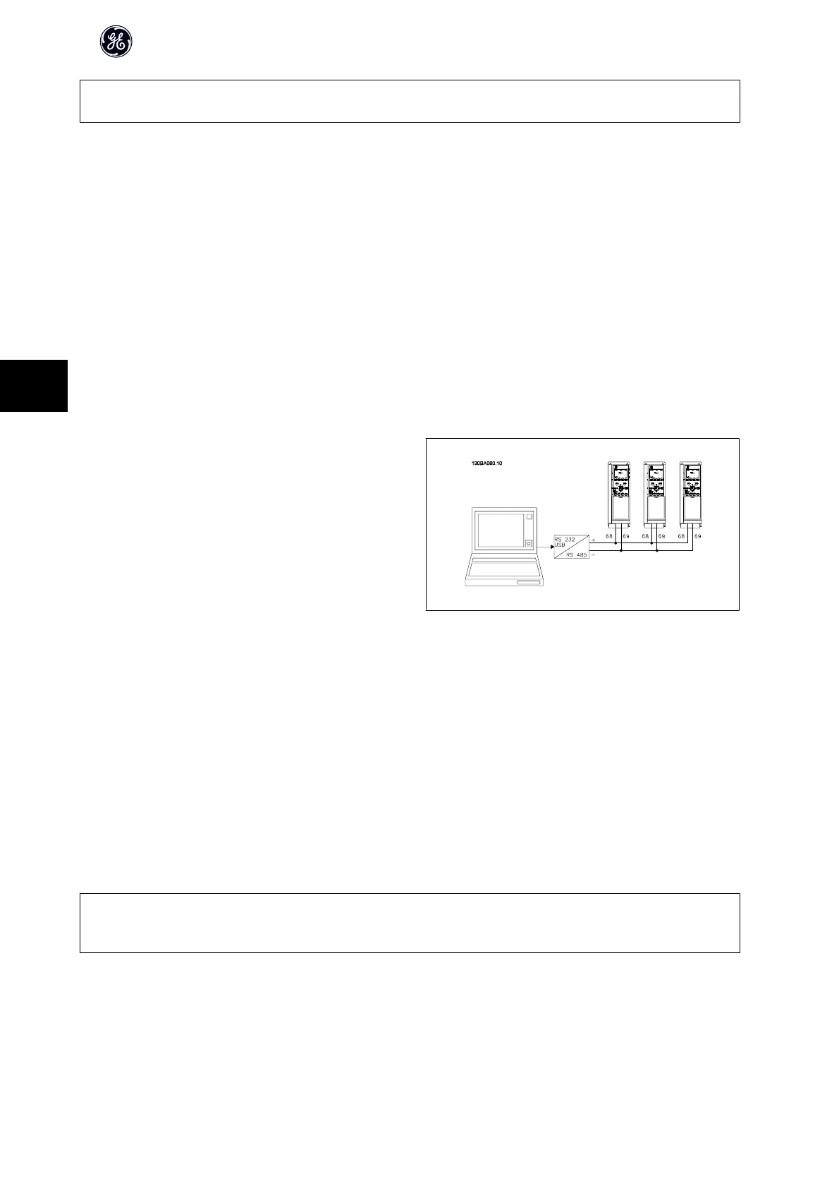
6.1.3 RS-485 Bus Connection
One or more frequency converters can be connected to a controller (or mas-
ter) using the RS-485 standard interface. Terminal 68 is connected to the P
signal (TX+, RX+), while terminal 69 is connected to the N signal (TX-,RX-).
If more than one frequency converter is connected to a master, use parallel
connections.
Illustration 6.6: Connection example.
In order to avoid potential equalizing currents in the screen, earth the cable screen via terminal 61, which is connected to the frame via an RC-link.
Bus termination
The RS-485 bus must be terminated by a resistor network at both ends. If the drive is the first or the last device in the RS-485 loop, set the switch S801 on the
control card for ON.
For more information, see the paragraph Switches S201, S202, and S801.
6.1.4 How to Connect a PC to the frequency converter
To control or program the frequency converter from a PC, install the PC-based Drive Control Tool DCT 10..
The PC is connected via a standard (host/device) USB cable, or via the RS-485 interface as shown in the AF-600 FP Design Guide, chapter How to Install > Installation
of misc. connections.
NB!
The USB connection is galvanically isolated from the supply voltage (PELV) and other high-voltage terminals. The USB connection is connected to protection
earth on the frequency converter. Use only isolated laptop as PC connection to the USB connector on the frequency converter.
AF-600 FP High Power Operating Instructions
76
6
 Loading...


