Home
GE
Medical Equipment
LOGIQ P9
GE LOGIQ P9 Service Manual
4
of 1
of 1 rating
602 pages
Give review
Manual
Specs
To Next Page
To Next Page
To Previous Page
To Previous Page
Loading...
GE
RAFT
LOGIQ P9/P7
D
IRECTION
5604324
, R
EVISION
11
DRAFT
(J
ANUARY
24, 2019)
S
ERVICE
M
ANUAL
3-12
Section 3-6 - Con
nection of Auxiliary Devices
3-6-1
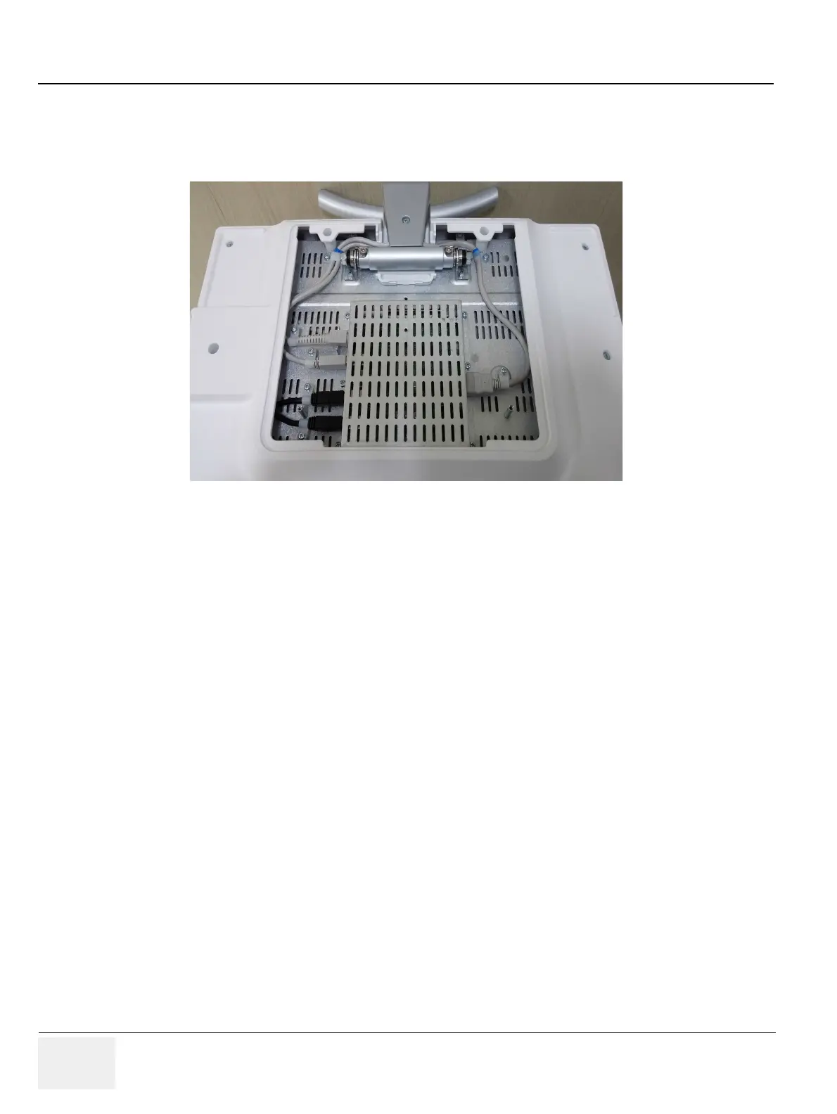
Connecting the LCD Monitor
NOTE:
The LCD monitor comes pre-insta
lled with the system.
Figure 3-5 Connect
ion Scheme - LCD Mon
itor
79
81
Table of Contents
Important Precautions
3
Chapter 1
41
Introduction
41
Section 1-1 Overview
41
1-1-1 Purpose of Chapter 1
41
1-1-2 Purpose of Service Manual
41
1-1-3 Typical Users of the Basic Service Manual
42
1-1-4 Models Covered by this Manual
42
1-1-5 Purpose of Operator Manual(s)
43
Section 1-2 Important Conventions
43
1-2-1 Conventions Used in this Manual
43
1-2-2 Standard Hazard Icons
44
1-2-3 Product Icons
45
Section 1-3 Safety Considerations
48
1-3-1 Introduction
48
1-3-2 Human Safety
48
1-3-3 Mechanical Safety
48
1-3-4 Electrical Safety
49
1-3-4-1 Safe Practices
49
1-3-4-2 Probes
49
1-3-5 Auxiliary Devices Safety
50
1-3-6 Battery Safety
52
1-3-7 Labels Locations
53
1-3-8 Dangerous Procedure Warnings
55
1-3-9 Lockout/Tagout Requirements (For USA Only)
55
1-3-10 Returning/Shipping System, Probes and Repair Parts
55
Section 1-4 Electromagnetic Compatibility (EMC)
56
1-4-1 What is EMC?
56
1-4-2 Compliance
56
1-4-3 Electrostatic Discharge (ESD) Prevention
56
Section 1-5 Customer Assistance
57
1-5-1 Contact Information
57
1-5-2 System Manufacturer
57
Chapter 2
59
Site Preparation
59
Section 2-1 Overview
59
2-1-1 Purpose of Chapter 2
59
Section 2-2 General Console Requirements
60
2-2-1 Environmental Requirements
60
2-2-1-1 Cooling
60
2-2-1-2 Lighting
60
2-2-2 Electrical Requirements
60
2-2-2-1 LOGIQ P9/P7 Power Requirements
61
2-2-2-2 Inrush Current
61
2-2-2-3 Site Circuit Breaker
61
2-2-2-4 Site Power Outlets
61
2-2-2-5 Main Power Plug
61
2-2-3 EMI Limitations
62
2-2-4 Probe Environmental Requirements
63
2-2-5 Time and Manpower Requirements
63
2-2-6 System Specifications
64
2-2-6-1 Physical Dimensions of LOGIQ P9/P7
64
2-2-6-2 Acoustic Noise Output
64
2-2-6-3 Electrical Specifications
64
Section 2-3 Facility Needs
65
2-3-1 Purchaser Responsibilities
65
2-3-2 Mandatory Site Requirements
66
2-3-3 Site Recommendations
66
2-3-3-1 Recommended Ultrasound Room Layout
67
2-3-4 Networking Setup Requirements
68
2-3-4-1 Stand-alone Unit (without Network Connection)
68
2-3-4-2 Unit Connected to Hospital’s Network
68
2-3-4-3 Purpose of the DICOM Network Function
68
2-3-4-4 DICOM Option Pre-installation Requirements
68
Chapter 3
69
Setup Instructions
69
Section 3-1 Overview
69
3-1-1 The Purpose of Chapter 3
69
Section 3-2 Set Up Reminders
70
3-2-1 Average Installation Time
70
3-2-2 Installation Warnings
71
3-2-2-1 Moving/Lifting the System
71
3-2-2-2 System Acclimation Time
71
3-2-2-3 OPIO Position
71
3-2-2-4 Brake Pedal Operation
72
3-2-3 Safety Reminders
72
Section 3-3 Receiving and Unpacking the Equipment
73
Section 3-4 Packing materials - recycling information
76
Section 3-5 Preparing for Set Up
77
3-5-1 Verify Customer Order
77
3-5-2 EMI Protection
78
Section 3-6 Connection of Auxiliary Devices
79
3-6-1 Connecting the LCD Monitor
80
3-6-2 Connecting the Black & White Printer
81
3-6-2-1 Connection Scheme: B&W Printer
82
3-6-3 Connecting the Secondary “Patient” LCD Monitor
83
3-6-4 Connecting the Footswitch
85
3-6-5 Connecting the USB Flash Memory Stick
86
3-6-6 Connecting the external USB Hard disk (Handydrive)
86
3-6-7 General Remarks and Hints when using external USB-Devices
87
3-6-7-1 External USB-Devices - Connection
87
3-6-7-2 External USB-Devices - Disconnection
87
Section 3-7 Completing the Set Up
88
3-7-1 Connecting the Unit to a Power Source
88
3-7-2 Power On / Boot Up
89
3-7-2-1 Scanner Power On
89
3-7-2-2 Back End Processor Boot Up
90
3-7-2-3 During a normal boot, you may observe
91
3-7-3 Power Off / Shutdown
93
3-7-3-1 Scanner Shutdown
95
3-7-4 Transducer Connection
98
3-7-4-1 Connecting the Probe
98
3-7-4-2 Connecting the CW Pencil Probe
99
3-7-4-3 Cable Handling
99
3-7-4-4 Activating the Probe
99
3-7-4-5 Deactivating the Probe
99
3-7-4-6 Disconnecting the Probe
99
Section 3-8 Printer Installation
100
3-8-1 Installing Digital Black & White Printer Sony UP-D898
100
3-8-2 Digital Color Printer Sony UP-D25MD
101
3-8-3 Installing the Bluetooth Deskjet Printer
102
3-8-3-1 Connecting the Bluetooth Dongle into the System
102
3-8-3-2 Verifying Bluetooth device driver
103
3-8-3-3 Prepare the Printer and connect the Bluetooth Printer Adapter
104
3-8-4 Adding Printer to the system
105
3-8-5 Adjustment of Printer Settings
105
3-8-5-1 UP-D898 - Printer Settings
106
3-8-5-2 UP-D25MD - Printer Settings
107
3-8-6 Setting Printer to Print Reports
109
3-8-6-1 Setting up the Printer to Print Reports
109
Section 3-9 System Configuration
110
3-9-1 System/General Preset Menu
110
3-9-2 External I/O Connectors
114
Section 3-10 Available Probes
115
3-10-1 Supported probes
115
3-10-1-1 Probe Naming Conventions
115
3-10-1-2 Probe Description
115
Section 3-11 Software/Option Configuration
121
Section 3-12 Connectivity Setup
122
3-12-1 Connectivity Introduction
122
3-12-1-1 The Dataflow Concept
122
3-12-1-2 Dataflow Examples
123
3-12-1-3 Stand-alone LOGIQ P9/P7
124
3-12-1-4 LOGIQ� + PC within a “Sneaker Net”
124
3-12-1-5 Connection between LOGIQ� and DICOM Server
124
3-12-2 Wired Ethernet from LOGIQ P9/P7 to a Workstation
125
3-12-2-1 Direct Cable Connection from the LOGIQ P9/P7 to a Workstation via a Crossover Cable.
125
3-12-2-2 Connection via a Peer-to-Peer Network
125
3-12-2-3 Connection via Hospital Network
125
3-12-2-4 You will need one network cable to connect the LOGIQ P9/P7 to a wall outlet on the hospital’s network.
125
3-12-3 Connection using Wireless Option
125
Section 3-13 Configuring Connectivity
126
3-13-1 Overview
126
3-13-2 Structured Reporting
126
3-13-2-1 Supported parameters
126
3-13-3 Connectivity Functions
127
3-13-4 TCPIP
128
3-13-5 Device
130
3-13-6 Service
131
3-13-6-1 Adding a service to a destination device
131
3-13-6-2 Removing a service
131
3-13-6-3 Changing parameters for a service
132
Section 3-14 Agent Configuration (R3 only)
133
3-14-1 Agent Configuration (R3 only)
133
3-14-1-1 Agent Configuration
133
3-14-1-2 Verifying Back Office Connection - CSD
135
3-14-1-3 Verifying Back Office Connection – VOC
136
Section 3-15 Connectivity Setup Worksheet
138
Section 3-16 Paperwork
140
3-16-1 Product Locator Installation
140
3-16-2 User Manual(s)
140
Chapter 4
141
Functional Checks
141
Section 4-1 Overview
141
4-1-1 Purpose of Chapter 4
141
Section 4-2 Required Equipment
141
Section 4-3 General Procedure
143
4-3-1 System Exterior Visual Check
144
4-3-1-1 Physical Abnormalities
144
4-3-1-2 Appearance Inspection
145
4-3-1-3 Appearance Inspection (R3)
146
4-3-2 Mechanical Parts Functional Check
147
4-3-2-1 Main LCD
148
4-3-2-2 LCD ARM
149
4-3-2-3 OPIO Swivel Lock
150
4-3-2-4 Swivel/Brake Lock Caster
151
4-3-2-5 Swivel/Brake Lock Caster
152
4-3-3 Power On/Off
153
4-3-3-1 Scanner Power On
153
4-3-3-2 Sleep Mode Check
155
4-3-3-3 Complete power down
156
4-3-3-4 Power Off / Shutdown Check
157
4-3-4 System Information
158
4-3-4-1 Software Version
158
4-3-4-2 Service Platform Confirmation (R1, R2, R2.5 only)
159
4-3-4-3 USB Port Test
160
4-3-5 System Integration Checks
161
4-3-5-1 OPIO Test
161
4-3-5-2 DVD Drive Test
162
4-3-5-3 LAN Port Test
162
4-3-6 Peripheral Checks
163
4-3-6-1 DVR Test (if equipped)
163
4-3-6-2 Black and White Printer Test
163
4-3-6-3 Color Printer Test
163
4-3-6-4 CD/DVD Read/WriteTest
163
4-3-6-5 ECG Test
163
4-3-6-6 Gel Warmer Test
164
4-3-6-7 Single CWD
164
4-3-7 Mode Transition Checks
164
4-3-7-1 General Information
164
4-3-7-2 B-Mode
166
4-3-7-3 Color Flow-Mode
167
4-3-7-4 Pulse Doppler Mode
168
4-3-7-5 B/CF/PW Mode
168
4-3-7-6 M-Mode
170
4-3-7-7 B-Flow Mode
170
4-3-7-8 CW Mode (Optional)
171
4-3-7-9 WLAN (Optional)
172
4-3-7-10 4D Mode (Optional)
172
4-3-7-11 Power Assistant (Optional)
172
4-3-8 OPIO Interface Check (R1, R2, R2.5 only)
173
4-3-9 OPIO Interface Check (R3 only)
176
4-3-10 Touch Panel Calibration (R3 only)
179
Section 4-4 Board Diagnostics
182
Chapter 5
185
Components and Functions (Theory)
185
Section 5-1 Overview
185
5-1-1 Purpose of Chapter 5
185
Section 5-2 General Information
186
5-2-1 System Exterior
186
5-2-2 Operator Panel
187
5-2-3 System Options
189
5-2-4 System Ports
190
5-2-4-1 Front USB
191
5-2-4-2 Rear USB and LAN
191
5-2-4-3 HDMI
193
5-2-4-4 S-Video / Composite
194
5-2-4-5 AC Inlet
195
Section 5-3 Power ON Sequence
196
Section 5-4 Software Options
197
5-4-1 Options
197
5-4-2 Smart Devices Applications (LOGIQ Apps)
200
Section 5-5 Hardware Options
201
5-5-1 Options
201
Section 5-6 Regional and Peripheral Options
203
5-6-1 Regional Options
203
5-6-2 Peripheral Options
203
Section 5-7 Mechanical Descriptions
204
5-7-1 Physical Dimensions
204
5-7-2 LCD Monitor
204
5-7-3 OPIO Positioning
204
5-7-4 Air Flow Distribution
205
Section 5-8 Exiting to Windows Desktop
206
5-8-1 Exiting to Windows Desktop
206
Section 5-9 Service Platform
208
5-9-1 Introduction
208
5-9-2 Access / Security
208
5-9-2-1 Local Access
208
5-9-2-2 How the Customer enables/disables Disruptive Mode and VCO
209
Section 5-10 Common Service Desktop (CSD) (R1, R2, R2.5 only)
210
5-10-1 Internationalization
210
5-10-2 CSD Top Page
211
5-10-2-1 General Layout
211
5-10-2-2 Decoding System Temperature and Voltage
212
5-10-3 Error Logs
214
5-10-4 Diagnostics
214
5-10-5 Image Quality
215
5-10-6 Configuration
216
5-10-7 Utilities
217
5-10-7-1 Disk Defragmenter
217
5-10-8 Replacement
219
5-10-9 PM
219
Section 5-11 Common Service Desktop (R3 only)
220
5-11-1 Purpose of this section
220
5-11-2 Disruptive mode
220
5-11-3 Color statuses
221
5-11-4 Licenses
221
5-11-5 Advanced Information - Service Desktop and SSA (Secure Service Access)
225
5-11-6 Home
226
5-11-7 Diags
248
5-11-8 DICOM
253
5-11-9 Utilities
257
5-11-10 Options
283
5-11-11 Agent Configuration
285
Chapter 6
287
Service Adjustments
287
Section 6-1 Overview
287
6-1-1 Purpose of Chapter 6
287
Section 6-2 Regulatory
287
Section 6-3 LCD Monitor Adjustment
288
6-3-1 Brightness/Contrast (R1.x.x)
290
6-3-1-1 Brightness
290
6-3-2 OSD Control on the Utility mode (R1.x.x)
291
6-3-3 21.5 inch Wide Monitor Adjustment (R2.x.x and later)
292
6-3-3-1 Scan Screen
294
6-3-3-2 Room Profile
294
6-3-3-3 Color Profile
294
Chapter 7
295
Diagnostics/Troubleshooting
295
Section 7-1 Overview
295
7-1-1 Purpose of Chapter 7
295
7-1-2 Overview
295
Section 7-2 Collect Vital System Information
296
7-2-1 Collecting System Information
296
7-2-2 Request for Service (RFS) (R1, R2, R2.5 only)
297
7-2-3 Request for Service (RFS) (R3 only)
299
7-2-3-1 Request for Service
299
Section 7-3 Check Points Voltages
301
7-3-1 LED for Power Status
301
Section 7-4 Screen Captures and Logs
302
7-4-1 Capturing a screen
302
7-4-2 Export Log’s and System Data
302
7-4-2-1 Export System Data (by pressing the ALT + D key)
302
7-4-3 System Warning/Errors and Logs
303
7-4-3-1 Temperature warning
303
7-4-3-2 Temperature exceeded threshold
303
7-4-3-3 System voltage failure
304
7-4-3-4 Hardware configuration error
305
7-4-3-5 System Error
306
Section 7-5 Remote Access to Service Platform
309
7-5-1 General
309
7-5-2 How the Customer enables/disables Disruptive Mode and VCO
310
7-5-3 GE Icon and Remote Connection
310
7-5-4 Customer Granting Full Remote Access Permission to GE Service Technician
311
7-5-4-1 If GE Service Technician requests Remote Access Permission
311
7-5-5 Common Service Desktop (CSD)
312
7-5-6 CSD: Configuration
312
Section 7-6 Minimum Configuration to Boot/Scan
313
Section 7-7 Troubleshooting Trees, Instructions and Tech Tips
314
7-7-1 System does not boot up
315
7-7-2 Noise disturbs the image
316
7-7-3 Trackball - Impaired Sensitivity
317
7-7-4 Printer Malfunction
318
7-7-5 Monitor Troubleshooting
319
7-7-6 How to import patient data base from older consoles
319
7-7-7 EZbackup will not delete images to open disk space
319
7-7-8 Use ScLogWindow
320
7-7-9 SSA key
323
7-7-10 Log analysis
324
Chapter 8
327
Replacement Procedures
327
Section 8-1 Overview
327
8-1-1 Purpose of Chapter 8
327
8-1-2 Returning/Shipping System, Probes and Repair Parts
330
Section 8-2 Warnings and important information
331
8-2-1 Purpose of this section
331
8-2-2 Warnings
331
8-2-3 Returning/Shipping Probes and Repair Parts
332
Section 8-3 System Software - Installation/Upgrade Procedure
333
8-3-1 Introduction
333
8-3-2 Manpower
333
8-3-3 Tools
333
8-3-4 Preparations
333
8-3-5 Preparation
333
8-3-5-1 General Notes on LOGIS P7/P9 Software Loading
333
8-3-5-2 Preparation for Software Loading
335
8-3-6 System Software - Installation Procedure
351
8-3-7 Software Installation from DVD
352
8-3-7-1 System Software - Installation Procedure (R1.x.x)
352
8-3-7-2 System Software - Installation Procedure (R2.x.x)
358
8-3-7-3 System Software - Installation Procedure (R3.x.x)
364
8-3-7-4 Application Software Installation Preparation (R1.x.x or R2.x.x)
369
8-3-7-5 Application Software Installation (R1.x.x or R2.x.x)
370
8-3-7-6 Software DVD / USB Storage
372
8-3-8 Software Installation from Common Service Desktop (R1.x.x or R2.x.x)
374
8-3-8-1 Involking Software Reload
374
8-3-9 Software Installation from Common Service Desktop (R3.x.x)
377
8-3-10 System Setup Procedure to display the messages in Japanese/Chinese
378
Section 8-4 Software and Functional Checks after Installation Procedure
382
8-4-1 Functional Check
382
Section 8-5 Settings - Backup and Restore
383
8-5-1 General Information
384
8-5-1-1 Supported Media
384
8-5-1-2 General Notes
384
8-5-2 Backup Procedures
384
8-5-3 Restore Procedures
385
8-5-4 EZBackup and EZMove
385
8-5-4-1 EZBackup and EZMove
385
8-5-4-2 To review EZBackup and EZMove
386
8-5-5 Option Keys
387
Section 8-6 Replacement of Front Cover
388
8-6-1 Manpower
388
8-6-2 Tools
388
8-6-3 Removal Procedure
388
8-6-4 Installation Procedure
389
8-6-5 Functional Check
389
Section 8-7 Replacement of Top Cover
390
8-7-1 Manpower
390
8-7-2 Tools
390
8-7-3 Removal Procedure
390
8-7-4 Installation Procedure
391
8-7-5 Functional Check
391
Section 8-8 Replacement of Side Cover
392
8-8-1 Manpower
392
8-8-2 Tools
392
8-8-3 Removal Procedure
392
8-8-3-1 Removal Procedure - Side Cover (L)
392
8-8-3-2 Removal Procedure - Side Cover (R)
394
8-8-4 Installation Procedure
395
8-8-5 Functional Check
395
Section 8-9 Replacement of Rear Cover
396
8-9-1 Manpower
396
8-9-2 Tools
396
8-9-3 Removal Procedure
396
8-9-4 Installation Procedure
396
8-9-5 Functional Check
396
Section 8-10 Replacement of Side Tray & Foot Rest Cover
397
8-10-1 Manpower
397
8-10-2 Tools
397
8-10-3 Removal Procedure
397
8-10-3-1 Removal Procedure - Side Tray.
397
8-10-3-2 Removal Procedure - Foot Rest Cover
398
8-10-4 Installation Procedure
398
Section 8-11 Replacement of Monitor and LCD Arm Plastic Covers
399
8-11-1 Manpower
399
8-11-2 Tools
399
8-11-3 Preparations
399
8-11-4 Monitor Remove Procedure
399
8-11-5 Monitor Installation Procedure
401
8-11-6 LCD Arm Plastic Covers Remove Procedure
402
8-11-7 LCD Arm Plastic Covers Installation Procedure
403
Section 8-12 Replacement of Monitor Covers
404
8-12-1 Manpower
404
8-12-2 Tools
404
8-12-3 Pre-Work
404
8-12-4 Removal Procedure
404
8-12-5 Installation Procedure
405
8-12-6 Functional Check
405
Section 8-13 Replacement of Fixed Arm Cover and Fixed Arm Holder Grip
406
8-13-1 Manpower
406
8-13-2 Tools
406
8-13-3 Removal Procedure
406
8-13-3-1 Removal Procedure - Fixed Arm Cover
406
8-13-3-2 Removal Procedure - Fixed Arm Holder Grip
406
8-13-4 Installation Procedure
407
8-13-5 Functional Check
407
Section 8-14 Replacement of OPIO and Related Parts
408
8-14-1 Manpower
408
8-14-2 Tools
408
8-14-3 Removal Procedure
408
8-14-3-1 Removal Procedure - Trackball Ring
409
8-14-3-2 Removal Procedure - OP Panel Assy
409
8-14-3-3 Removal Procedure - AN Keyboard (Option)
412
8-14-3-4 Removal Procedure - Trackball
413
8-14-3-5 Removal Procedure - LCD Touch Panel Assy
414
8-14-3-6 Removal Procedure - Freeze key assy
415
8-14-3-7 Removal Procedure - OP Panel Main PWA Assy
416
8-14-3-8 Removal Procedure - Encoder on PWA
419
8-14-3-9 Removal Procedure - Touch panel
419
8-14-4 Installation Procedure
420
8-14-5 Functional Check
421
Section 8-15 Replacement of the Caps for Hardkeys
422
8-15-1 Manpower
422
8-15-2 Tools
422
8-15-3 Removal Procedure
422
8-15-4 Installation Procedure
422
8-15-5 Functional Check
423
Section 8-16 Replacement of Key Caps (by special native language keys)
424
8-16-1 Manpower
424
8-16-2 Tools
424
8-16-3 Preparations
424
8-16-4 Removal Procedure
424
8-16-5 Installation Procedure
425
8-16-6 Replacement Checking Procedure
425
8-16-7 Functional Check
426
Section 8-17 Replacement around Nest Box
427
8-17-1 Manpower
427
8-17-2 Tools
427
8-17-3 Pre-Work
427
8-17-4 Nest Box Access
427
8-17-5 Removal Procedure - Nest Box
429
8-17-6 Installation Procedure - Nest Box.
430
8-17-7 Removal Procedure - Board Assy in Nest Box
431
8-17-8 Removal Procedure - Separating MPI and MCB
433
8-17-9 Removal Procedure - Separating DCWD Board(Option) from MPI
434
8-17-10 Separating MDC assy from MCB assy
435
8-17-11 Handling EEPROM on MCB Board
436
8-17-12 Separating MCB assy from Brackets and COM Express
437
8-17-13 Separating DC4D Unit from IO BOX
439
8-17-14 Separating Battery Unit from IO BOX
440
8-17-15 Separating HDD
441
8-17-16 Separating COM Express
442
8-17-17 Installation Procedure - MPI, MCB, MDC, DC4D, HDD, Battery and COM Express
443
8-17-18 Functional Check - MPI, MCB, MDC, IO Box
443
8-17-19 Removal Procedure - MBP assy
443
8-17-20 Installation Procedure - MBP assy
443
8-17-21 Functional Check
443
Section 8-18 Replacement of Front fan
444
8-18-1 Manpower
444
8-18-2 Tools
444
8-18-3 Removal Procedure
444
8-18-4 Installation Procedure
444
8-18-5 Functional Check
444
Section 8-19 Replacement of Bottom fan
445
8-19-1 Manpower
445
8-19-2 Tools
445
8-19-3 Removal Procedure
445
8-19-4 Installation Procedure
447
8-19-5 Functional Check
447
Section 8-20 Replacement of Rear Handle
448
8-20-1 Manpower
448
8-20-2 Tools
448
8-20-3 Removal Procedure
448
8-20-4 Installation Procedure
448
8-20-5 Functional Check
448
Section 8-21 Replacement of Link Arm Cable Hook
449
8-21-1 Manpower
449
8-21-2 Tools
449
8-21-3 Removal Procedure
449
8-21-4 Installation Procedure
449
8-21-5 Functional Check
449
Section 8-22 Replacement of Caster
450
8-22-1 Manpower
450
8-22-2 Tools
450
8-22-3 Removal Procedure
450
8-22-4 Installation Procedure
452
8-22-5 Functional Check
452
Section 8-23 Replacement of the COM Express
453
8-23-1 Manpower
453
8-23-2 Tools
453
8-23-3 Removal Procedure
453
8-23-4 Installation Procedure
455
8-23-5 Note on COM Express Replacement
455
8-23-5-1 Configuring BIOS
455
8-23-6 Note on EEPROM Replacement
456
8-23-6-1 Accessing EEPROM
457
8-23-6-2 Initializing EEPROM
458
8-23-6-3 Modifying contents of EEPROM (ComExpress VPD)
460
8-23-7 Functional Check
460
Section 8-24 Replacement of the HDD/SSD
461
8-24-1 Manpower
461
8-24-2 Tools
461
8-24-3 Removal Procedure
461
8-24-4 Installation Procedure
462
8-24-5 Functional Check
462
Section 8-25 Replacement of Battery
463
8-25-1 Manpower
463
8-25-2 Tools
463
8-25-3 Removal Procedure
463
8-25-4 Installation Procedure
464
8-25-5 Functional Check
464
Section 8-26 Replacement of 4D
465
8-26-1 Manpower
465
8-26-2 Tools
465
8-26-3 Removal Procedure
465
8-26-4 Installation Procedure
466
8-26-5 Functional Check
466
Section 8-27 Replacement of Wireless LAN
467
8-27-1 Manpower
467
8-27-2 Tools
467
8-27-3 Removal Procedure
467
8-27-4 Installation Procedure
467
8-27-5 Functional Check
467
Section 8-28 Replacement of the Harness Cable and OPIO Cable Assy
468
8-28-1 Manpower
468
8-28-2 Tools
468
8-28-3 Pre-Work
468
8-28-4 Removal Procedure (Harness Cable Assy)
468
8-28-5 Removal Procedure (OPIO Cable Assy)
470
8-28-6 Installation Procedure
470
8-28-7 Functional Check
471
Section 8-29 Replacement of Peripheral Cable Assy
472
8-29-1 DVD Cables
472
8-29-1-1 Manpower
472
8-29-1-2 Tools
472
8-29-1-3 Pre work
472
8-29-1-4 Removal Procedure
472
8-29-1-5 Installation Procedure
474
8-29-2 B/W Printer Cables
475
8-29-2-1 Manpower
475
8-29-2-2 Tools
475
8-29-2-3 Pre work
475
8-29-2-4 Removal Procedure
475
8-29-2-5 Installation Procedure
478
8-29-2-6 Functional Check
478
Section 8-30 Replacement of the Probe Holder
479
8-30-1 Manpower
479
8-30-2 Tools
479
8-30-3 Removal Procedure
479
8-30-4 Installation Procedure
479
8-30-5 Functional Check
479
Section 8-31 Replacement of the Cable Hook
480
8-31-1 Manpower
480
8-31-2 Tools
480
8-31-3 Removal Procedure
480
8-31-4 Installation Procedure
480
8-31-5 Functional Check
480
Section 8-32 Replacement of the OPIO Tray
481
8-32-1 Manpower
481
8-32-2 Tools
481
8-32-3 Removal Procedure
481
8-32-4 Installation Procedure
481
8-32-5 Functional Check
481
Section 8-33 Replacement of the Paper tray
482
8-33-1 Manpower
482
8-33-2 Tools
482
8-33-3 Removal Procedure
482
8-33-4 Installation Procedure
482
8-33-5 Functional Check
482
Section 8-34 Replacement of AC Cable Holder
483
8-34-1 Manpower
483
8-34-2 Tools
483
8-34-3 Removal Procedure
483
8-34-4 Installation Procedure
483
8-34-5 Functional Check
483
Section 8-35 Replacement of the BW printer
484
8-35-1 Manpower
484
8-35-2 Tools
484
8-35-3 Pre work
484
8-35-4 Removal Procedure
484
8-35-5 Installation Procedure
485
8-35-6 Functional Check
485
Section 8-36 Replacement of the Speaker
486
8-36-1 Manpower
486
8-36-2 Tools
486
8-36-3 Pre work
486
8-36-4 Removal Procedure
486
8-36-5 Installation
489
8-36-6 Functional Check
489
Section 8-37 Replacement of the Monitor Arm
490
8-37-1 Manpower
490
8-37-2 Tools
490
8-37-3 Removal Procedure
490
8-37-4 Installation Procedure
490
8-37-5 Functional Check
490
Section 8-38 Replacement of Front Fan Filter
491
8-38-1 Manpower
491
8-38-2 Tools
491
8-38-3 Removal Procedure
491
8-38-4 Installation Procedure
491
8-38-5 Functional Check
491
Section 8-39 Replacement of Bottom Fan Filter
492
8-39-1 Manpower
492
8-39-2 Tools
492
8-39-3 Removal Procedure
492
8-39-4 Installation Procedure
492
8-39-5 Functional Check
492
Section 8-40 Replacement of SW CD set (R1, R2, R2.5 only) and SW USB (R3 only)
493
8-40-1 Manpower
493
8-40-2 Tools
493
8-40-3 Removal Procedure
493
8-40-4 Installation Procedure
493
8-40-5 Functional Check
493
Section 8-41 Replacement of Drawer
494
8-41-1 Manpower
494
8-41-2 Tools
494
8-41-3 Removal Procedure
494
8-41-4 Installation Procedure
495
8-41-5 Functional Check
495
Section 8-42 Replacement of ECG
496
8-42-1 Manpower
496
8-42-2 Tools
496
8-42-3 Removal Procedure
496
8-42-4 Installation Procedure
497
8-42-5 Functional Check
497
Section 8-43 Replacement of DCWD ASSY
498
8-43-1 Manpower
498
8-43-2 Tools
498
8-43-3 Removal Procedure
498
8-43-4 Installation Procedure
499
8-43-5 Functional Check
499
Section 8-44 Replacement of MCWD ASSY
500
8-44-1 Manpower
500
8-44-2 Tools
500
8-44-3 Removal Procedure
500
8-44-4 Installation Procedure
500
8-44-5 Functional Check
500
Section 8-45 Replacement of battery pack for LP7-P9 R2 ext battery pack
501
8-45-1 Manpower
501
8-45-2 Tools
501
8-45-3 Removal Procedure
501
8-45-4 Installation Procedure
504
8-45-5 Functional Check
504
Section 8-46 Replacement of battery pack for LP7-P9 R2 Battery option
506
8-46-1 Manpower
506
8-46-2 Tools
506
8-46-3 Removal Procedure
506
8-46-4 Installation Procedure
508
8-46-5 Functional Check
509
Section 8-47 Replacement of MBOB
510
8-47-1 Manpower
510
8-47-2 Tools
510
8-47-3 Removal Procedure
510
8-47-4 Installation Procedure
514
8-47-5 Functional Check
514
Section 8-48 Replacement of MIO-B
515
8-48-1 Manpower
515
8-48-2 Tools
515
8-48-3 Removal Procedure
515
8-48-4 Installation Procedure
517
8-48-5 Functional Check
517
Section 8-49 Replacement of BBC
518
8-49-1 Manpower
518
8-49-2 Tools
518
8-49-3 Removal Procedure
518
8-49-4 Installation Procedure
523
8-49-5 Functional Check
523
Section 8-50 Replacement of LOGIQ P9 ROTATION MODULE KIT
524
8-50-1 Manpower
524
8-50-2 Tools
524
8-50-3 Removal Procedure
524
8-50-4 Installation Procedure
529
8-50-5 Functional Check
529
Section 8-51 Replacement of ODD Dummy Cover R3
530
8-51-1 Manpower
530
8-51-2 Tools
530
8-51-3 Pre work
530
8-51-4 Removal Procedure
530
8-51-5 Installation Procedure
530
8-51-6 Functional Check
530
Section 8-52 Replacement of Probe Light assy
531
8-52-1 Manpower
531
8-52-2 Tools
531
8-52-3 Pre work
531
8-52-4 Removal Procedure
531
Chapter 9
533
Renewal Parts
533
Section 9-1 Overview
533
9-1-1 Purpose of Chapter 9
533
Section 9-2 List of Abbreviations
534
Section 9-3 LOGIQ P9/P7 Software
535
Section 9-4 Parts List Groups
536
Section 9-5 Plastics Covers (Front/Sides/Rear)
538
9-5-1 Plastics Covers (Front/Sides/Rear) (R1 ~ R2.5)
538
9-5-2 Plastics Covers (Front/Sides/Rear) (R3)
540
Section 9-6 LCD Monitor
542
Section 9-7 OPIO
544
Section 9-8 Nest Box Parts
549
Section 9-9 Mechanical Part
553
Section 9-10 Options
556
Section 9-11 Optional Peripherals and Accessories
561
9-11-1 Printers
561
Section 9-12 Probes
562
Section 9-13 Power Cord
563
Chapter 10
565
Care & Maintenance
565
Section 10-1 Overview
565
10-1-1 Preventive Maintenance Inspections
565
10-1-2 Purpose of Chapter 10
565
Section 10-2 Why do Maintenance
566
10-2-1 Quality Assurance
566
Section 10-3 Maintenance Task Schedule
566
10-3-1 How often should care & maintenance tasks be performed?
566
Section 10-4 Tools Required
569
10-4-1 Special Tools, Supplies and Equipment
569
10-4-1-1 Specific Requirements for Care & Maintenance
569
Section 10-5 System Maintenance
570
10-5-1 Preliminary Checks
570
10-5-2 Functional Checks
571
10-5-2-1 System Checks
571
10-5-2-2 Peripheral/Option Checks
572
10-5-3 Input Power
572
10-5-3-1 Mains Cable Inspection
572
10-5-4 Cleaning
572
10-5-4-1 General Cleaning
572
10-5-4-2 Air filter cleaning
573
10-5-5 Physical Inspection
574
10-5-6 Optional Diagnostic Checks
574
10-5-6-1 View the logs
574
10-5-7 Probe Maintenance
575
10-5-7-1 Probe Related Checks
575
10-5-7-2 Basic Probe Care
575
10-5-7-3 Basic Probe Cleaning and/or Disinfection
575
Section 10-6 System Software Updates(Software Download) (R1, R2, R2.5 only)
576
10-6-1 Software download and installation
577
Section 10-7 Using a Phantom
585
Section 10-8 Electrical Safety Tests
585
10-8-1 Safety Test Overview
585
10-8-2 GEHC Leakage Current Limits
586
10-8-3 Outlet Test - Wiring Arrangement - USA & Canada
588
10-8-4 Grounding Continuity
589
10-8-4-1 Meter Procedure
589
10-8-5 Enclosure Leakage Current Test
590
10-8-5-1 Definition
590
10-8-5-2 Generic Procedure
590
10-8-5-3 Data Sheet for Enclosure Leakage Current
591
10-8-6 Earth Leakage Current Test
591
10-8-6-1 Definition
591
10-8-6-2 Generic Procedure
592
10-8-7 Type BF Patient Leakage Current Test - Probe
593
10-8-7-1 Definition
593
10-8-7-2 Generic Procedure on Leakage Current
593
10-8-8 Type BF Patient Leakage current - Mains to Probe
595
Section 10-9 When There’s Too Much Leakage Current...
596
10-9-1 Earth and/or Enclosure Fails
596
10-9-2 Probe Fails
596
10-9-3 Peripheral Fails
596
10-9-4 Still Fails
596
10-9-5 New Unit
597
Section 10-10 Ultrasound INSPECTION CERTIFICATE
599
Other manuals for GE LOGIQ P9
Technical Publication
127 pages
4
Based on 1 rating
Ask a question
Give review
Questions and Answers:
Need help?
Do you have a question about the GE LOGIQ P9 and is the answer not in the manual?
Ask a question
GE LOGIQ P9 Specifications
General
Brand
GE
Model
LOGIQ P9
Category
Medical Equipment
Language
English
Related product manuals
GE LOGIQ P7
602 pages
GE LOGIQ P6
478 pages
GE LOGIQ P5
532 pages
GE LOGIQ P3 PRO
348 pages
GE LOGIQ P3 VET
348 pages
GE LOGIQ P6 Series
484 pages
GE LOGIQ P3 EXPERT
348 pages
GE LOGIQ P5 Basic OB
532 pages
GE LOGIQ P6 Pro Series
484 pages
GE LOGIQ A5
127 pages
GE LOGIQ V2
317 pages
GE LOGIQ E10
778 pages

 Loading...


