GE H
EALTHCARE
D
IRECTION
GA091568, R
EVISION
5 VIVID E9 S
ERVICE
M
ANUAL
5 - 46 Section 5-8 - Front End Processor (FEP)
5-8-7-7 LEDs on the DRX board - the GDIF status display
Programming status LEDs exist on the left side of the board. They indicate the programming status of
the GDIF FPGA.
GDIF debug LEDs exist near the lower left side of the board. They are used for GDIF status display.
5-8-7-8 Troubleshooting hints
• During power up, the 4 x 4 LEDs (see Figure 5-31 "LEDs for Nathan (beamforming) circuits" on
page 5-45) will be stable ON. If they blink at this time, it indicates an error.
• During scanning the 4 x 4 LEDs will blink: LEDs in first column will turn ON, then the LEDs in the
next column are lit, then the LEDs in the third column and at last the LEDs in the fourth row. Next,
the sequence will repeat.
• If the card starts, the voltages are OK.
• If it is artifacts in the picture (during scanning), you may try to interchange the position for the DRX
boards, and scan again. If the artifacts moves to the left or to the right, it indicates an error on a
DRX. If the artifact don’t move, the problem is elsewhere in the signal chain.
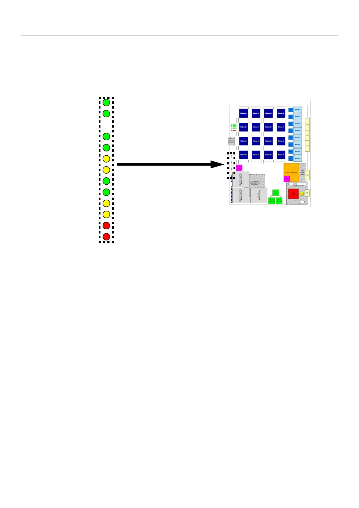
Figure 5-32 GDIF status display
GDIF LED 0
GDIF LED 1
GDIF LED 2
GDIF LED 3
GDIF LED 4
GDIF LED 5
GDIF LED 6
GDIF LED 7
GDIF LED 8
GDIF LED 9
TOP MGT 1 LINK UP
TOP MGT 2 LINK UP
TOP MGT 3 LINK UP
TOP MGT 3 LINK UP
BOTTOM MGT 1 LINK UP
BOTTOM MGT 2 LINK UP
BOTTOM MGT 3 LINK UP
BOTTOM MGT 4 LINK UP
BOARD LAST IN CHAIN
ERROR CONDITION
INT
DONE

 Loading...


