GE H
EALTHCARE
D
IRECTION
GA091568, R
EVISION
5 VIVID E9 S
ERVICE
M
ANUAL
8 - 60 Section 8-5 - Replacing Covers and Bumpers
8-5-13 Rear Handle replacement
8-5-13-1 Preparations
When preparing for the replacement, you must perform the following steps:
1.) Power down the VIVID E9
2.) Disconnect the Mains Power Cable from the wall outlet.
3.) Disconnect all probes and external I/O cabling.
4.) Remove the Side Covers.
5.) Remove the Rear Cover.
6.) Remove the Top Cover.
8-5-13-2 Rear Handle removal procedure
Follow these steps to remove the Rear Handle:
1.) Remove the 2 upper screws, one on each side.
2.) Remove the 4 lower screws, two on each side.
3.) Lift the Rear Handle away.
8-5-13-3 Rear Handle installation procedure
Follow these steps to install the Rear Handle:
1.) Install the Rear handle in position so its fastening holes are flush with the holes in the frame.
WARNINGWARNING
ENERGY CONTROL AND POWER LOCKOUT FOR VIVID E9.
WHEN SERVICING PARTS OF THE SYSTEM WHERE THERE IS EXPOSURE TO
VOLTAGE GREATER THAN 30 VOLTS:
1. FOLLOW LOCK OUT/TAG OUT PROCEDURES.
2. TURN OFF THE BREAKER.
3. UNPLUG THE VIVID E9.
4. MAINTAIN CONTROL OF THE POWER PLUG.
5. WAIT FOR AT LEAST 20 SECONDS FOR CAPACITORS TO DISCHARGE, AS THERE ARE NO TEST POINTS TO
VERIFY ISOLATION. THE AMBER LIGHT ON THE OP PANEL ON/OFF BUTTON WILL TURN OFF.
BEWARE THAT THE MAIN POWER SUPPLY AND BACK END PROCESSOR MAY BE ENERGIZED EVEN IF THE POWER
IS TURNED OFF WHEN THE CORD IS STILL PLUGGED INTO THE AC OUTLET.
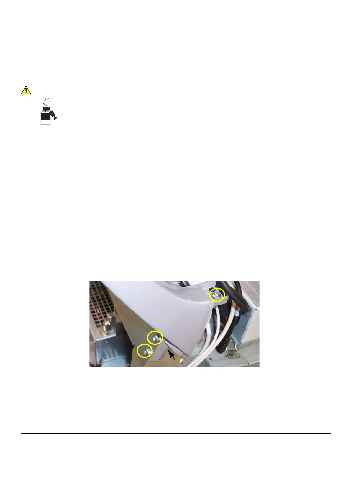
Figure 8-61 Three screws on each side (left side illustrated)
Signed
Date
TA G
&
LOCKOUT
2 OF 4
SCREWS
LEFT UPPER
SCREWS USED TO
SECURE THE REAR
HANDLE
TOP COVER
SCREW REMOVED
AREA SUPPORTED
WHEN
SCREWS ARE IN
PLACE

 Loading...


