GE H
EALTHCARE
D
IRECTION
GA091568, R
EVISION
5 VIVID E9 S
ERVICE
M
ANUAL
Chapter 5 - Components and functions (theory) 5 - 41
5-8-5 Receiver Board (GRX)
5-8-5-1 General description
The analog Receiver boards (GRX) receives the weak ultrasound echo signals from the probes, via the
Relay board and the XD bus on the Front Plane boards. The main task for the GRX boards are to do
Time Variable Amplification on the echo signals.
To support 192 analog receiving channels from the probes, two different GRX boards are used in
VIVID E9:
• 64 Channel Receiver board without analog CW Doppler
• 128 Channel Receiver board with analog CW Doppler
The 128 channel Receiver board also include the needed circuits to demodulate the CW Doppler signals
from a Pedof probe.
NOTE: Some probes, like the 3V and 4V, are pre-beamforming the received signals from the
transducer elements down to 192 channels. These 192 channels are connected to the system
as described above.
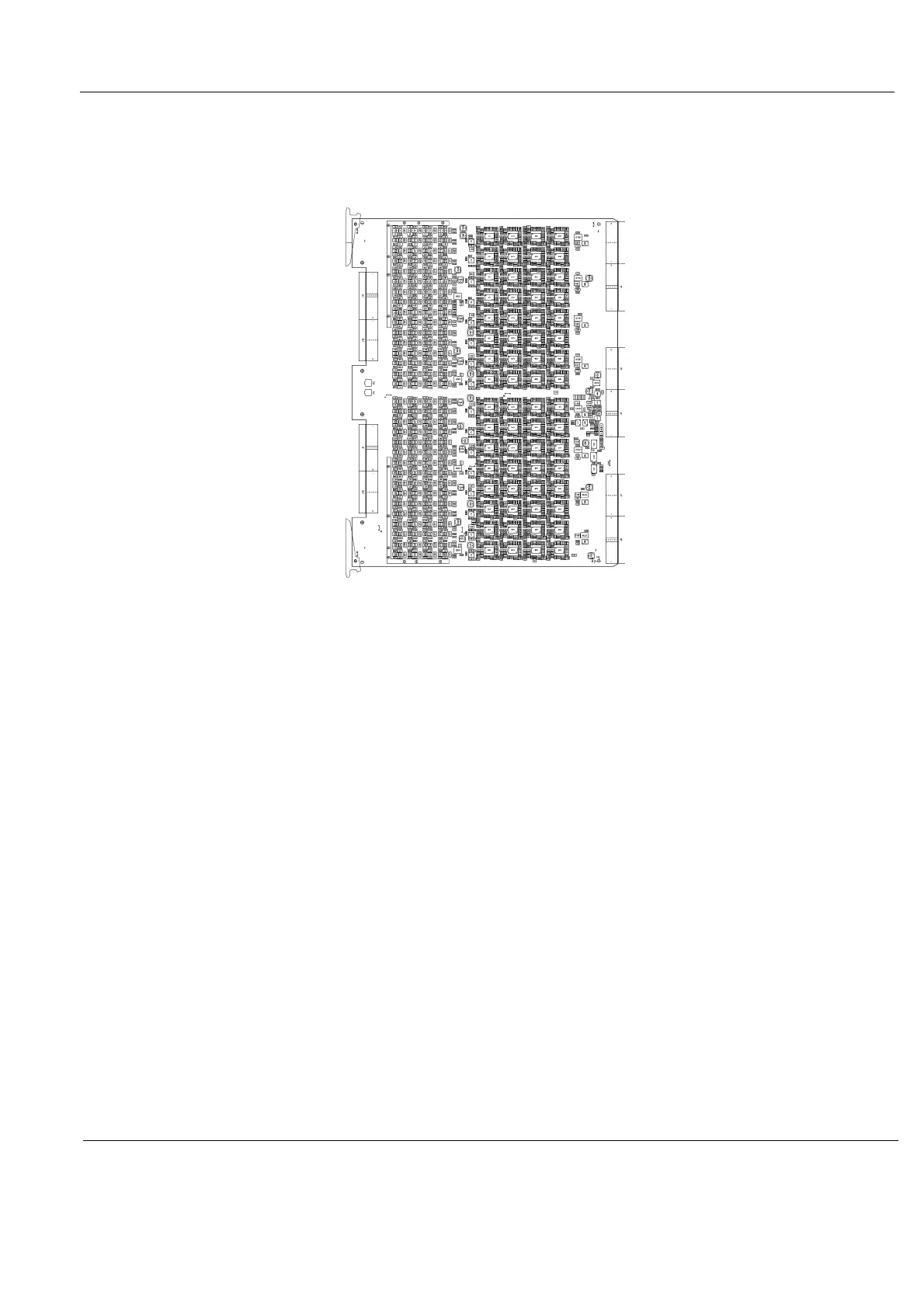
Figure 5-27 GRX board

 Loading...


