GE H
EALTHCARE
D
IRECTION
GA091568, R
EVISION
5 VIVID E9 S
ERVICE
M
ANUAL
Chapter 8 - Replacement procedures 8 - 127
8-6-16-3 Install the Operator Panel, Lower
Follow these steps to install the Operator Panel:
1.) Carefully, Slide in the Operator Panel. Lower.
Be careful with the fingers which have to be placed under the side walls of the UI Frame, Upper.
2.) On the Bulkhead Bracket, fasten the ESD wire from the Lower Panel.
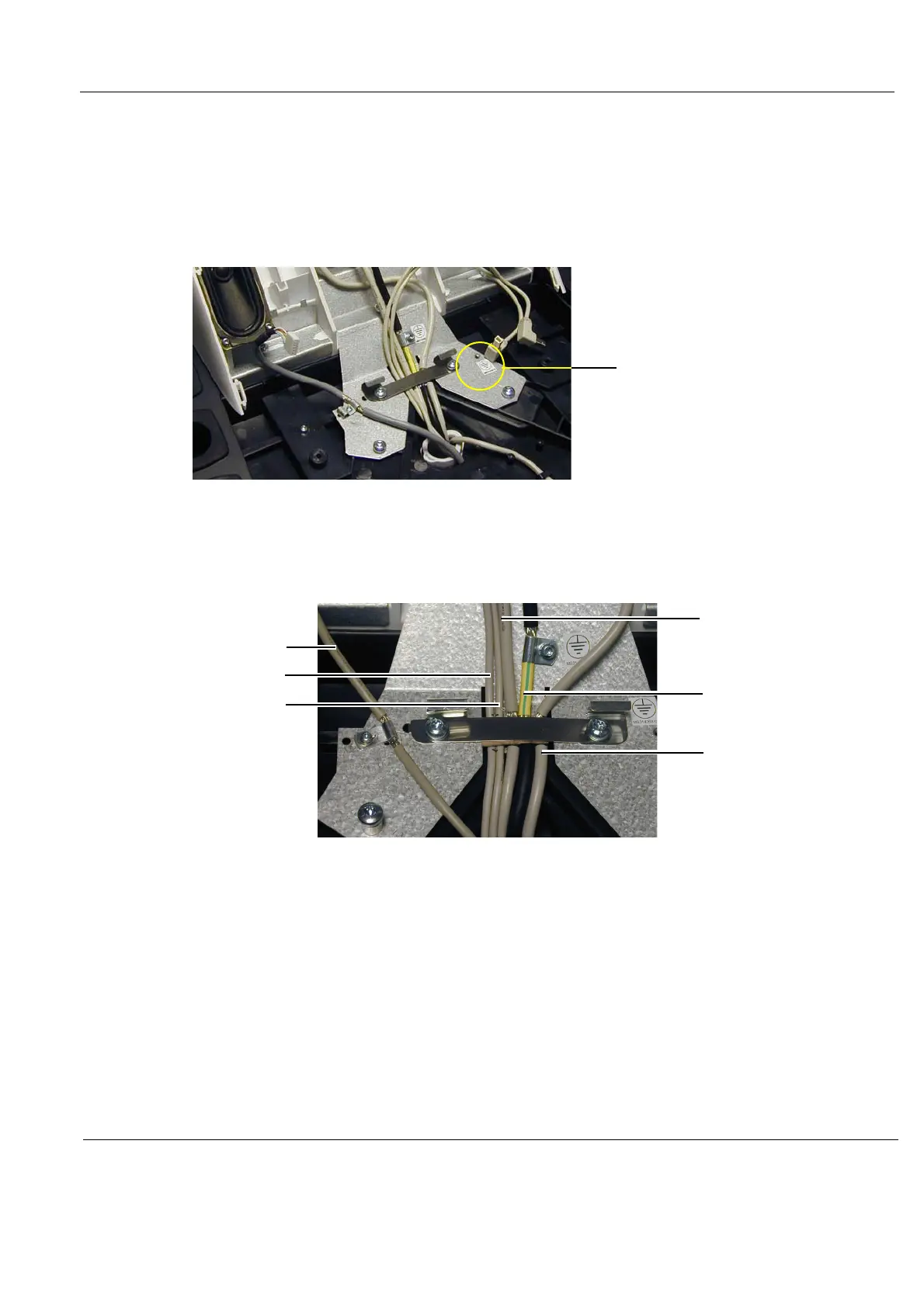
3.) Attach the cables to the cable grounding brackets/points, as illustrated below.
Since this feature is for the EMI compatibility the braid have to be exposed under the bracket and
the cables have to be well locked by the bracket.
4.) Install the four fixing screws that fix the Operator Panel assembly to the Operator Panel tray (2 pc.
M4x25 nearest to the front and 2 pc. M4 x 12 at the rear). The screws are entered from below the
Operator Panel tray.
5.) Install the Operator Panel, Upper.
Figure 8-141 Lower OP Grounding
Figure 8-142 OP Cables Grounding
1 - Cable, A/N Keybd.
2 - USB2
3 - USB1
4 - Bulkhead cable
5 - HDMI Cable
6 - OP Cable
YELLOW/GREEN GROUND WIRE FROM
LOWER OP HERE
(NOT ILLUSTRATED)
1
2
3
4
5
6

 Loading...


