GE H
EALTHCARE
D
IRECTION
GA091568, R
EVISION
5 VIVID E9 S
ERVICE
M
ANUAL
Chapter 8 - Replacement procedures 8 - 291
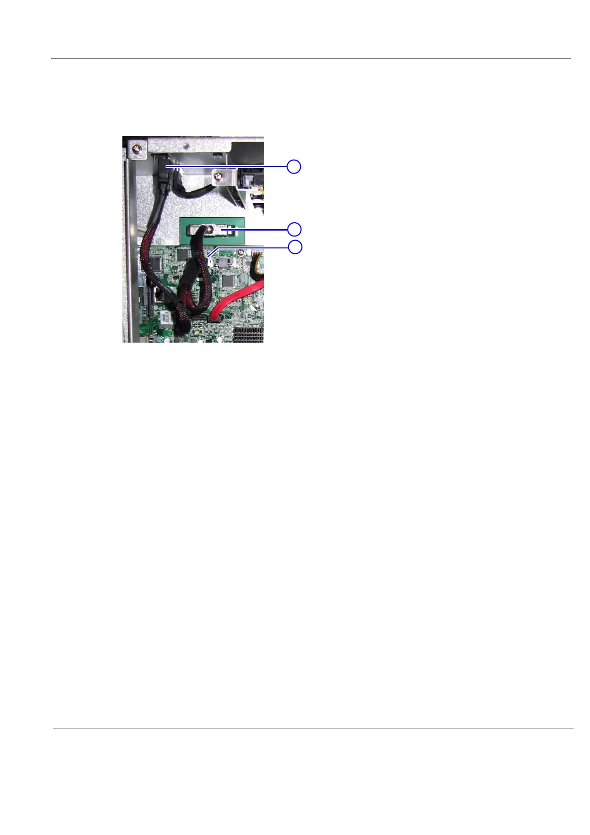
8-11-15-2 BEP6 to GFI and Card Rack Backplane Cable removal
1.) Reach inside the BEP and disconnect the Boundary Scan Cable from the FEP Backplane
Connector.
2.) Disconnect the plug from the PCIE L5 Connector on the BEP Motherboard.
3.) Unplug the GFI cable outside (on the top of) the BEP chassis.
4.) Unscrew the 3 mm fixing screw for the Chassis Connector.
You can now remove the BEP6 to GFI and Card Rack Backplane Cable.
8-11-15-3 BEP6 to GFI and Card Rack Backplane Cable installation
1.) Connect the Boundary Scan Cable to the FEP Backplane Connector.
2.) Connect the PCIE L5 plug to the PCIE L5 Connector on the BEP Motherboard.
3.) Position the Chassis Connector in the cut out in the chassis and fasten it with the 3 mm screw.
4.) Plug in the GFI PCIe Cable in the Chassis Connector (from the outside of the BEP chassis).
5.) Install the BEP Cover.
6.) Install the Left Side Cover.
Figure 8-244 Boundary Scan cable connects BEP to FEP Back Plane (BEP view)
1. Chassis Connector for PCIe to GFI
2. FEP Backplane Connector
3. PCIE L5 Connector
1
2
3

 Loading...


