Class VDI100 Model
Wire section (mm
2
)
Main circuit
(2)
Grounding line
E(G)
Control line
(3)
400V
3 Ph
VDI100-1007-KBX-4 2.5~6 2.5~6 0.5~2.5
VDI100-1015-KBX-4
2.5
~6 4~6 0.5~2.5
VDI100-1022-KBX-4 2.5
~6 4~6 0.5~2.5
VDI100-2037-KBX-4 2.5
~6 4~6 0.5~2.5
VDI100-2055-KBX-4 4
~6 4~6 0.5~2.5
VDI100-3075-KBX-4 6 6
0.5~2.5
VDI100-3110-KBX-4 10 10
0.5~2.5
VDI100-3150-KBX-4 10 10
0.5~2.5
VDI100-4185-KBX-4
10 10
0.5~2.5
VDI100-4220-KBX-4 16 10
0.5~2.5
VDI100-5300-KBX-4 25 10
0.5~2.5
VDI100-5370-KXX-4 25 16
0.5~2.5
VDI100-5450-KXX-4 35 16
0.5~2.5
VDI100-5550-KXX-4 70 25
0.5~2.5
VDI100-6750-KXX-4 95 25
0.5~2.5
VDI100-6900-KXX-4
150 25 0.5~2.5
VDI100-71100-KXX-4
150 25 0.5~2.5
VDI100-71320-KXX-4 240 35
0.5~2.5
VDI100-71600-KXX-4 300 35
0.5~2.5
(1): Constant torque rating.
(2): The main circuit terminals: R/L1, S/L2, T/L3, U/T1, V/T2, W/T3, B1/P, B2, -, o,+
(3): Control line is the terminal wire on the control board.
3.17. Control Circuit Wiring
(1) Separate the wiring for control circuit terminals from main circuit wiring for terminals (R/L1, S/L2, T/L3, U/
T1, V/T2, W/T3).
(2) Separate the wiring for control circuit terminals R1A-R1B-R1C (or R2A, R2C) (Relay outputs) from wiring for
terminals - , A01, A02, GND, DO1, DO2, DOG, +10V, (-10V), AI1, AI2 and GND wiring.
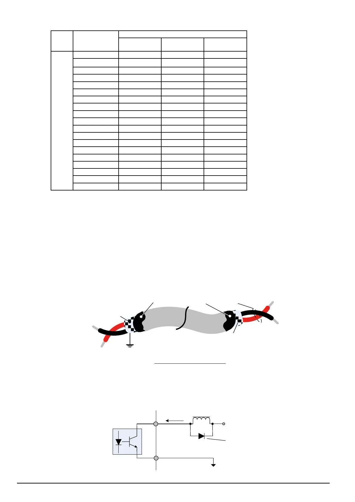
(3) Use shielded twisted-pair cables (#24 - #14 AWG / 0.5 -2 mm2) shown in Fig. 3.17.1 for control circuits to
minimize noise problems. The maximum wiring distance should not exceed 50m (165 ft).
Shield
Twisted Pair
Wrap with insulating Tape
Ground Shield at Inverter
end ONLY
DO NOT Ground Shield at
this end
Fig.3.17.1:ShieldedTwisted-Pair
(4) When the digital multi-function output terminals (DO1, DO2) are connected to an external relay, a free-
wheeling diode should be connected across the relay coil to prevent an inductive voltage spike from damag-
ing the output circuitry as shown in Fig. 3.17.2 below.
+ 48V max.
VDI100
DO1, DO2
Free-wheeling diode
(100V, > 100mA)
50 mA max.
Relay Coil
32 VDI100 • Instruction manual
 Loading...


