Fig.3.17.2:Photo-CouplerConnectedtoanExternalRelay
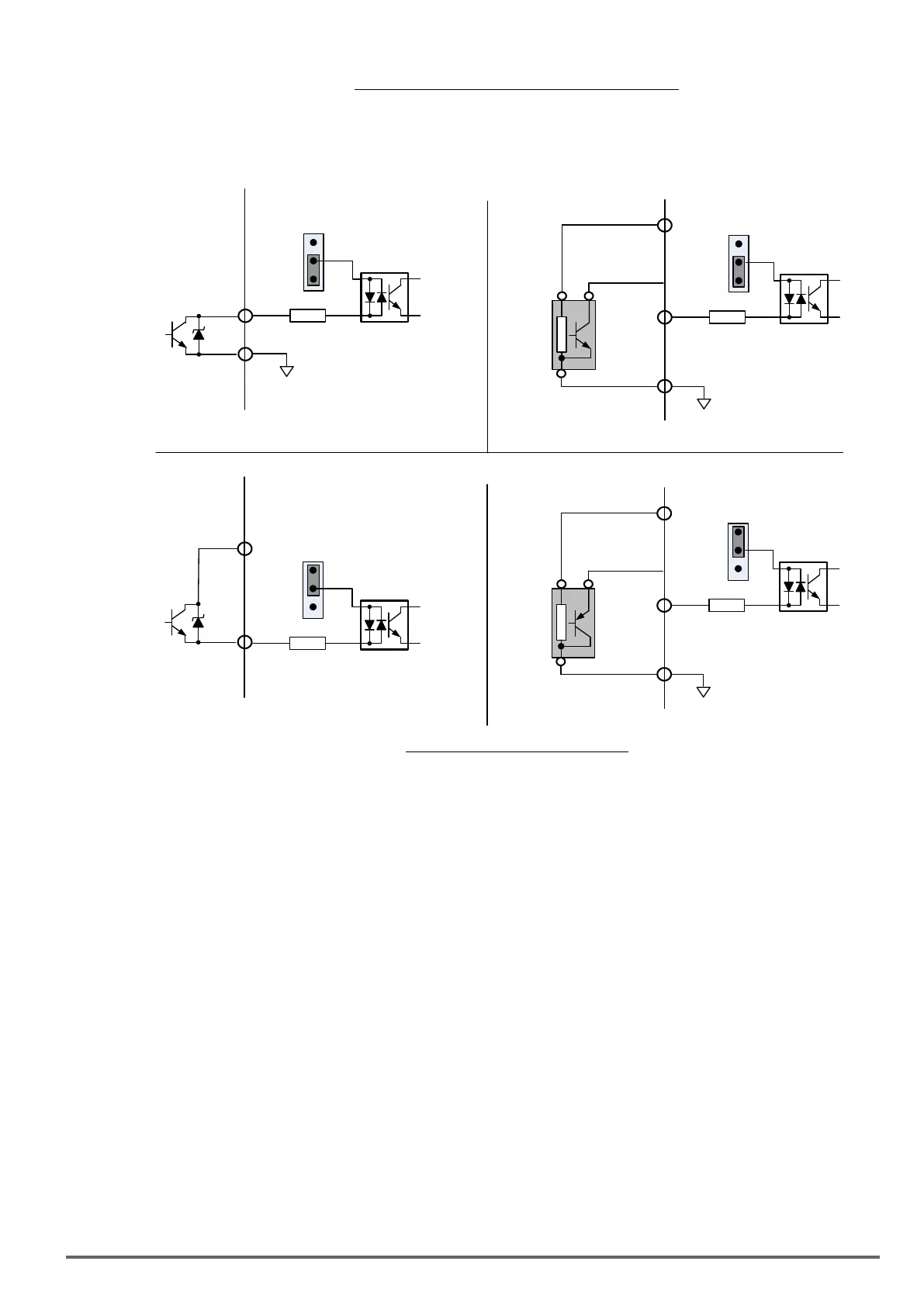
(5) In Section 3.8 the control boards referenced have a jumper SW3 that can select the digital input to terminals
- , to be set for SINK or SOURCE. The following Fig. 3.17.3 (a.) – (d.) shows examples for the various
SINK / Source interfaces.
24VG
Sink
Source
24VG
Sink
Source
NPN
+24V
Input Digital
Terminals S1 - S8
Input Digital
Terminals S1 - S8
(a.) Open Collector Interface
(b.) NPN Sensor Interface
+24V
Sink
Source
Input Digital
Terminals S1 - S8
(c.) Open Collector Interface
Source Configuration
(d.) PNP Sensor Interface
24VG
Sink
Source
PNP
+24V
Input Digital
Terminals S1 - S8
SW3
SW3
SW3
SW3
Fig.3.17.3:Sink/SourceCongurations
VDI100 • Instruction manual
33
 Loading...


