10
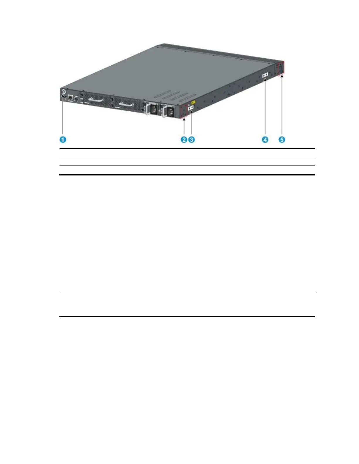
Figure 8 Identifying the mounting and grounding positions
(1) Auxiliary grounding point 2
(2) Rear mounting position
(3) Primary grounding point
(4) Auxiliary grounding point 1
(5) Front mounting position
Attaching the mounting brackets and chassis rails to the chassis
To attach the mounting brackets and chassis rails to the switch chassis:
1. Align the mounting brackets with the screw holes in the rear mounting position (see Figure 9) or
front mounting position (see Figure 10).
2. Use M4 screws (supplied with the switch) to attach the mounting brackets to the chassis.
3. Align the chassis rails with the rail mounting holes in the chassis:
If the mounting brackets are in the rear mounting position, align the chassis rails with the screw
holes at the front of the side panels (see Figure 9).
If the mounting brackets are in the front mounting position, align the chassis rails with the screw
holes at the rear of the side panels (see Figure 10).
4. Use M4 screws (supplied with the switch) to attach the chassis rails to the chassis.
NOTE:
Secure the mounting brackets and chassis rails to both sides of the chassis in the same way.
 Loading...


