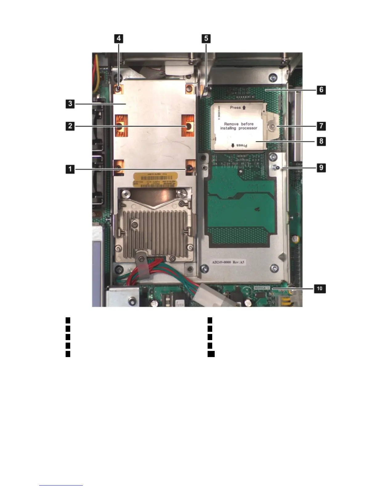
Figure 6-31 Processor ZIF Socket, and Alignment Holes and Posts
6
Processor slot 1
1
Alignment hole on processor
2
ZIF socket for processor 0
7
ZIF socket for processor 1
8
Processor slot 1 dust cover
3
Processor 0 (in slot 0)
4
Alignment hole on processor
9
Alignment post on processor cage
105
Processor 1 slot label (module 1)Alignment post on processor cage
Figure 6-32 shows the ZIF socket in the unlocked position.
Removing and Replacing a Processor 179
 Loading...