EasyManuals Logo
Home>Hypertherm>Welding System>SYNC Powermax 65

Hypertherm SYNC Powermax 65 User Manual

Hypertherm SYNC Powermax 65
174 pages
To Next Page IconTo Next Page
To Previous Page IconTo Previous Page
Page #69 background imageLoading...
Page #69 background image
Operate the Plasma System
3
Powermax65/85/105 SYNC Operator Manual 810470 69
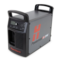
Step 4 – Set the power switch to ON (I)
Set the power switch to ON (I). The
switch is on the rear panel of the
plasma power supply.
If the torch-lock switch is set
to the green “ready to
fire” ( ) position when you
set the power switch to ON,
the hand torch puts out a
puff of air. Refer to Warning
puffs of air (hand torches) on
page 70.
If the torch-lock switch is set
to the yellow lock (X)
position when you set the
power switch to ON, the
0-50-0 or 0-50-1 fault code
and Torch Cap Sensor icon
show on the status screen.
Refer to Fault code and LED behavior on page 71.

Table of Contents

Other manuals for Hypertherm SYNC Powermax 65

Questions and Answers:

Question and Answer IconNeed help?

Do you have a question about the Hypertherm SYNC Powermax 65 and is the answer not in the manual?

Hypertherm SYNC Powermax 65 Specifications

General IconGeneral
BrandHypertherm
ModelSYNC Powermax 65
CategoryWelding System
LanguageEnglish

Related product manuals