EasyManuals Logo
Home>Image Access>Scanner>Bookeye 4

Image Access Bookeye 4 User Manual

Image Access Bookeye 4
122 pages
To Next Page IconTo Next Page
To Previous Page IconTo Previous Page
Page #25 background imageLoading...
Page #25 background image
Operation Manual Page 25
A.8.1 Connectors on the Rear Side
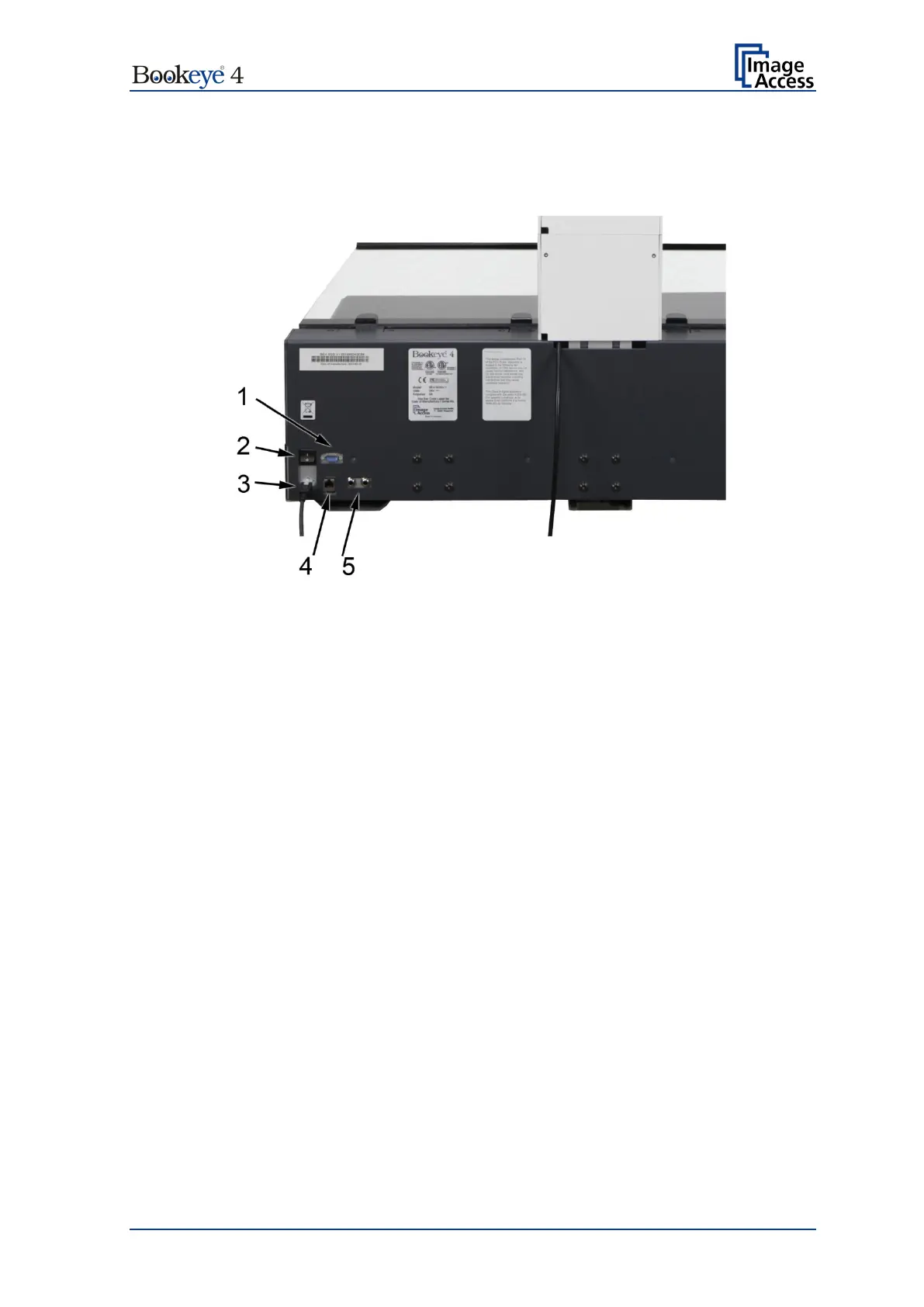
For easy orientation, the connectors found on the rear side of the scanner are depicted in
the following picture and described below.
Picture 3: Connectors on the rear side
1. Connector for Recovery key.
2. Main power switch. Set the main power switch to position I to set the Bookeye
®
4
scanner to standby mode.
3. Connector for external power supply.
4. Network connector. Insert a network cable for access to the scanner via the
integrated Scan2Net® user interface.
5. Two foot pedal connectors.

Table of Contents

Other manuals for Image Access Bookeye 4

Questions and Answers:

Question and Answer IconNeed help?

Do you have a question about the Image Access Bookeye 4 and is the answer not in the manual?

Image Access Bookeye 4 Specifications

General IconGeneral
BrandImage Access
ModelBookeye 4
CategoryScanner
LanguageEnglish

Related product manuals