Manual Page 23
Place the middle guide plate upside down on the front side guide plate.
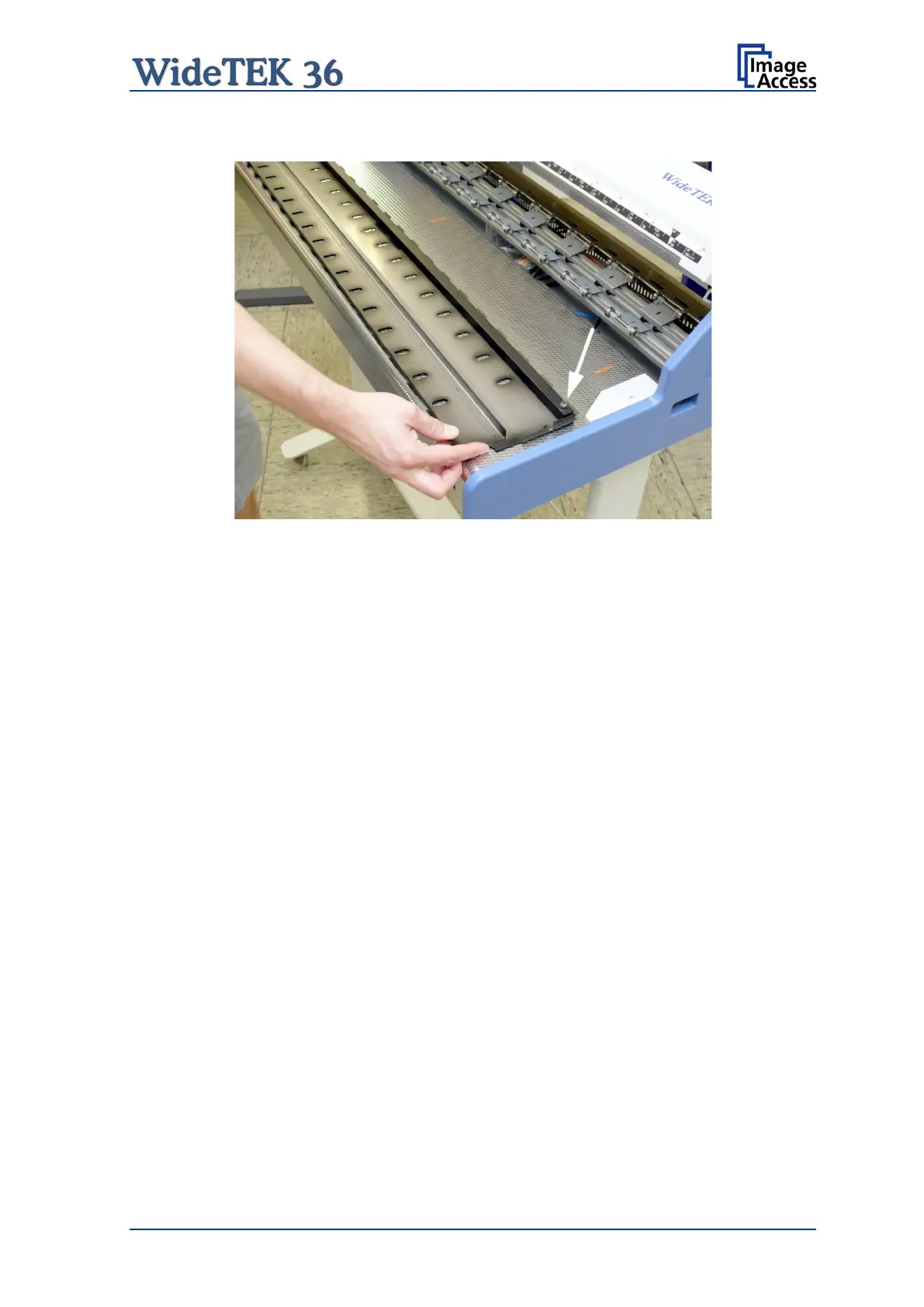
Picture 7: Self locking nut on the bottom side of middle guide plate
Use a 7 mm ring spanner wrench (not supplied) or a pair of pliers to loosen the self-
locking nuts. Less than one turn is enough.
The self-locking nuts only serve for transport security, to avoid loosening of the Allen head
screws and disconnection of the heavy steel square bar during transport.
After loosening the self-locking nuts, insert the middle guide plate in order to modify the
contact pressure.
Now move the Allen head screws to the desired position and check the contact pressure.
Refasten the Allen head screws after modifying the position of the metal ballast.
In a last step remove the guide plate as described above. Fasten the self-locking nuts at
both ends. Insert the guide plate again.
 Loading...