Intel® Server Board S2600CO Family TPS Functional Architecture Overview
Revision 1.0 23
Intel order number G42278-002
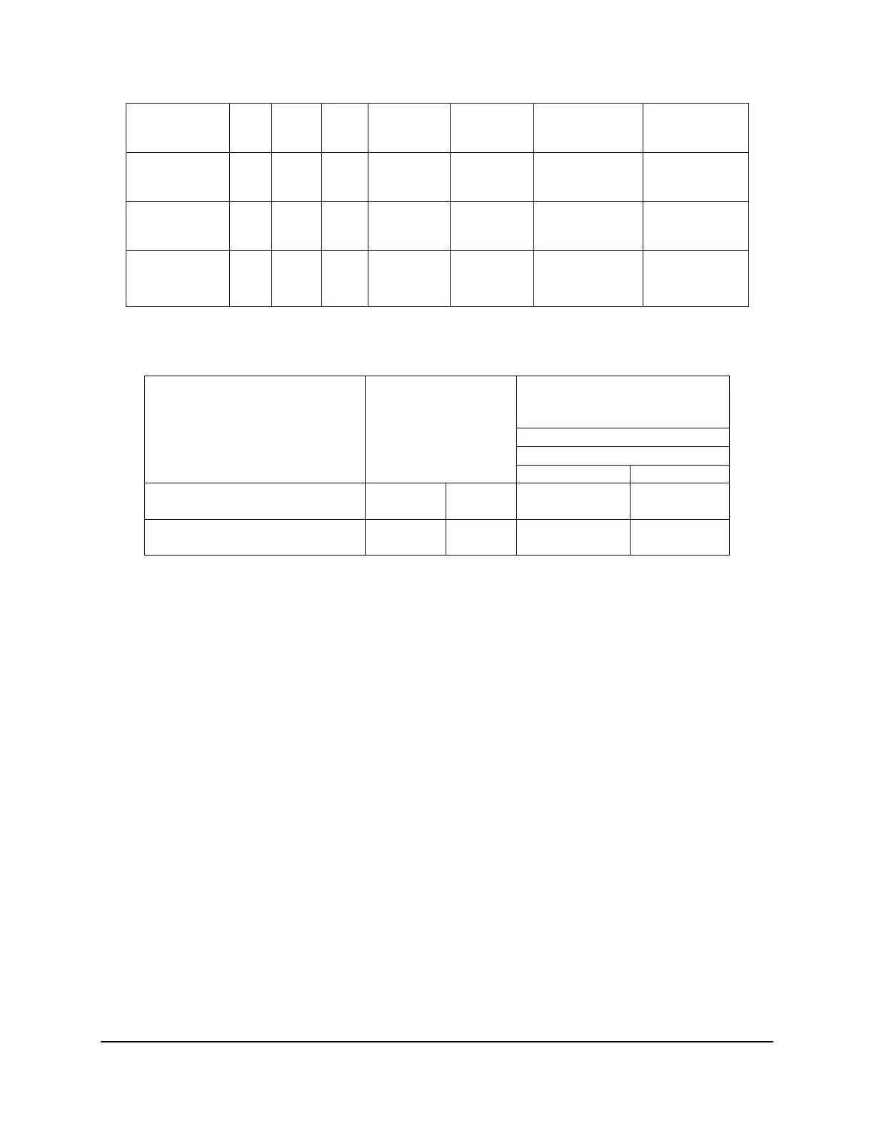
Table 5. LRDIMM Support Guidelines
Ranks Per DIMM and Data Width
1
Memory Capacity Per
DIMM
2
Speed (MT/s) and Voltage Validated by
Slot per Channel (SPC) and DIMM Per
Channel (DPC)
3,4,5
3.2.2.2 Memory Slot Identification and Population Rules
Note: Although mixed DIMM configurations may be functional, Intel only performs platform
validation on systems that are configured with identical DIMMs installed.
Each installed processor provides four channels of memory. On the Intel
®
Server Board
S2600CO each memory channel support 2 memory slots, for a total possible 16 DIMMs
installed.
System memory is organized into physical slots on DDR3 memory channels that belong
to processor sockets.
The memory channels from processor socket 1 are identified as Channel A, B, C and D.
The memory channels from processor socket 2 are identified as Channel E, F, G, and H.
Each memory slot on the server board is identified by channel and slot number within
that channel. For example, DIMM_A1 is the first slot on Channel A on processor 1;
DIMM_E1 is the first DIMM socket on Channel E on processor 2.
The memory slots associated with a given processor are unavailable if the
corresponding processor socket is not populated.
A processor may be installed without populating the associated memory slots provided a
second processor is installed with associated memory.
In this case, the memory is
shared by the processors.
However, the platform suffers performance degradation and
latency due to the remote memory.

 Loading...


